
IVCAD Suite Measurement Standard
Conduct advanced tests on RF transistors for model extraction, begin passive load pull measurements, and test and linearize RF power amplifiers.
Measure RF Transistors and Amplifiers
IVCAD Measurement Standard (IVT) offers advanced DC and RF measurement capabilities, such as synchronized pulsed IV and S parameters, allowing for the subsequent extraction of transistor models. To validate these models, load pull measurement data is required. IVCAD offers the most advanced industrial measurement solution for tuner control, enabling impedance sweeping and characterization in nonlinear conditions, while controlling a wide variety of test configurations (scalar or vector benches, harmonic control, etc.).
This module also allows for easy circuit measurement under various test conditions, with modulated signal control and digital predistortion functions to reveal the maximum performance of power amplifier circuits.
IVCAD Suite Measurement Standard - IVT
- Pulse IV and S-Parameter Measurements
- Load Pull Measurements
- Intermodulation and Spurious
- IQ Mod/Demod & DPD Control
A Game-Changer for GaN Transistor Characterization
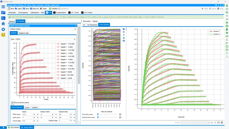
IVCAD Suite Measurement Standard (IVT) reshapes Pulsed IV measurements with the powerful AMCAD SAS’ Pulsed IV test system.
The current-voltage (IV) measurements play a crucial role in understanding how input and output currents and voltages interact in a device. For GaN Field Effect Transistors (FETs), this involves measuring output current based on varying input voltages, offering key insights into device performance.
Because of their ability to deliver high power, GaN devices are prone to self-heating and trapping effects, making careful voltage pulsing critical. By pulsing voltages between quiescent and hot values and adjusting pulse-widths, the average power delivered to the device is reduced, minimizing self-heating. This technique ensures near-isothermal performance, enabling more accurate and efficient testing.
IVCAD also enables the detection and visualization of trapping phenomena, such as gate and drain lag, in GaN transistors. It’s easy to observe how trapping effects evolve with different quiescent bias levels. Additionally, it supports full wafer control through seamless integration with various probe station software.
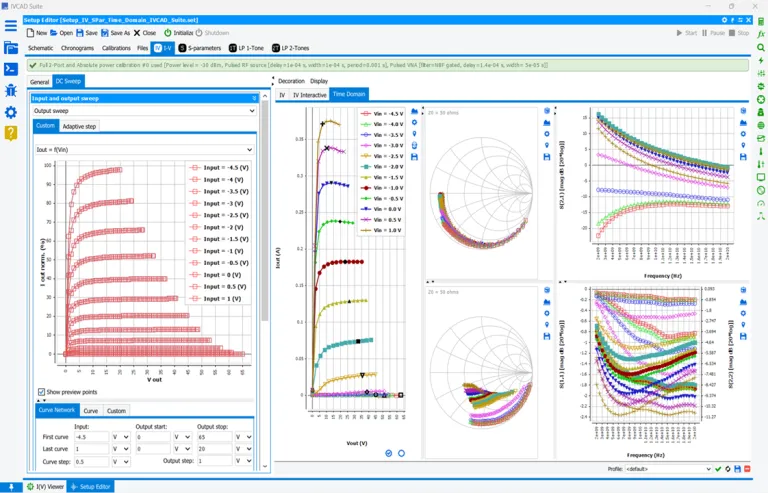
Synchronize Pulse IV and Pulse S Parameters
Unlike traditional S-parameters, which are measured under static conditions, Pulsed S-parameters can provide invaluable information to extract the equation parameters used for transistor compact modeling.
RF transistors, such as those in power amplifiers, often experience significant temperature variations and power fluctuations during operation. Traditional, continuous S-parameter measurements fail to capture the true performance of these devices under dynamic operating conditions when a large RF signal is applied across the IV current source.
Pulsing the input signal allows engineers to observe the transistor’s response for quasi-isothermal conditions, which enable an electrothermal description of the transistor behavior, and to extract nonlinear equations such as nonlinear capacitances.
These measurements are crucial because Pulsed S parameters reveal the transient effects that occur when RF transistors are driven hard, including the impact of self-heating, and other nonlinear behaviors. Without pulsed testing, engineers risk missing critical performance degradation that can affect device efficiency, reliability, and longevity
A Key Technique for Accurate RF Transistor Characterization
Load Pull is an essential technique for characterizing RF transistors, especially when operating in the nonlinear or large-signal region. S parameters provide valid results only in the linear region, where RF transistors are inefficient and output minimal power.
Load Pull accurately measures devices under real-world, high-power conditions, making it the preferred choice for assessing transistors in RF Power Amplifier applications. When a transistor operates with a large signal, Load Pull is the only reliable method to simulate application-like conditions and predict key RF specifications.
By using a software-controlled Load Pull setup, engineers can quickly characterize a Device Under Test (DUT), identify the optimum operating conditions, and design power amplifiers in a fraction of the time, dramatically reducing the design cycle and ensuring maximum performance.
For RF Power Amplifier designs, Load Pull measurements can be performed under Continuous Wave (CW) or Pulsed CW conditions, depending on the DUT power and thermal dissipation. Pulsed CW measurements help mitigate thermal effects, allowing for more accurate assessments of device performance under extreme conditions.
The key to effective Load Pull measurements is selecting the right configuration, balancing frequency coverage, power handling, accuracy, and ease of operation to meet specific testing requirements.
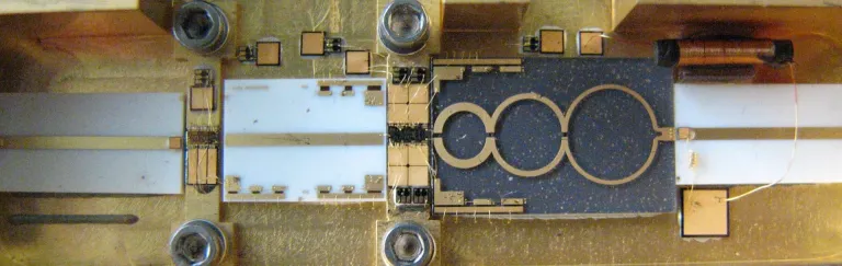
Make It Simple with Few Hardware
Traditional Load Pull, or Scalar Load Pull, was the first system to measure device performances automatically under various source and load impedances. The scalar setup can use coaxial or waveguide tuners. These test benches use pre-characterized passive tuners for impedance matching and scalar power detectors for measurements. Based on the pre-characterization of the impedance tuners, the measurements rely on the set of measured or interpolated s-parameters at different impedance conditions.
Raw measurements from scalar instruments (power meters) are de-embedded, in real-time, to the DUT reference plane using the loss calculation of tuners and other components in the setup. The accuracy of the measurements relies entirely on the calibration quality and the tuners’ mechanical repeatability. Therefore, building a mechanical tuner requires a high level of expertise.
The scalar load-pull architecture is cost-effective and can be advantageously driven using IVCAD Suite Measurement Standard (IVT).
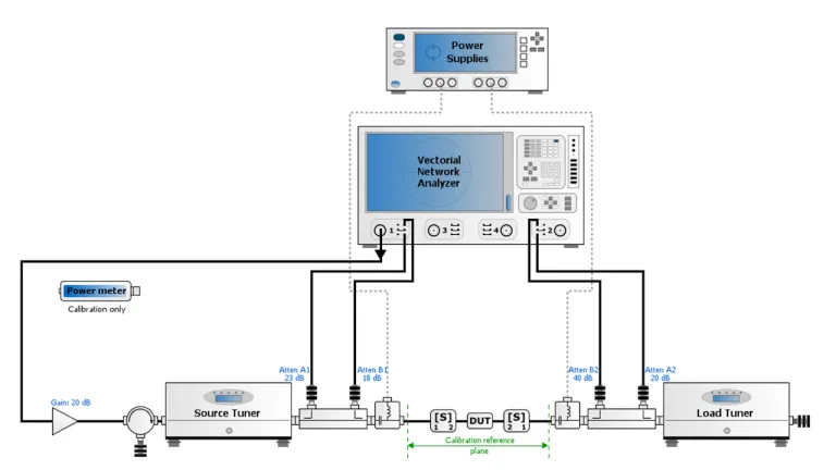
Use a Vector Network Analyzer for Nonlinear Characterization
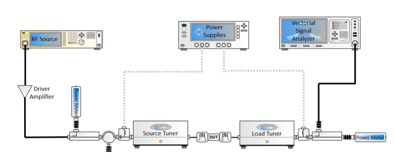
With the advent of new Vector Network Analyzer technologies, device characterization benches shifted to Vector Receiver Load Pull (VRLP) for a much more complete characterization technique. It allows extracting parameters not possible to measure with a Scalar Setup, like AMPM curves. Therefore, most of the load pull setups built nowadays are Vector based.
The IVCAD IVT module offers a modern and efficient methodology for load-pull measurements using low-loss couplers, inserted between the tuners and DUT. The VNA allows real-time measurement of a and b-waves at the DUT reference plane, enabling vector information not normally made available with traditional setups.
This setup architecture measures the load impedance presented to the DUT without prior assumptions of tuner characterization, positioning, or losses. Extremely accurate transistor input impedance derived from the a-and b-waves results in properly defined delivered input power, power added efficiency, and power gain measurements. At fundamental and harmonics, Output powers are made available along with multi-tone carrier and intermodulation products.
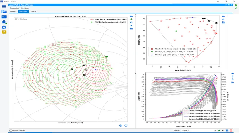
Find a Needle in a Haystack
Load Pull measurement data can be challenging to handle for several reasons, primarily due to the complexity of the measurements themselves and the need for precise interpretation of the results.
Load Pull testing involves sweeping various parameters (such as frequency, power, impedance, and bias conditions) and can generate large datasets. Finding the key information among this huge quantity of data that can be overwhelming. Incorrect analysis can lead to misleading conclusions about the transistor's performance.
- Interpolation: The first need is to ensure that the data can be interpolated under a wide variety of test conditions to learn how the transistors perform under conditions that were not used during the test campaign.
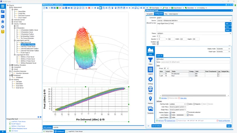
- In-depth Analysis: Based on the daily support provided to customers worldwide for decades by the AMCAD Engineering teams, IVCAD offers ready-to-use measurement analysis templates that will reveal the optimal performance that a transistor can deliver when correctly matched.
Analyzing the data to determine the optimal operating point for a given RF device or amplifier design requires detailed, methodical interpretation. In addition to the Whiteboard tool provided with the Front-End module (IVF), the load pull analysis templates provided with IVCAD Suite Measurement Standard (IVT) will secure and speed-up the handling of your load pull measurement data.
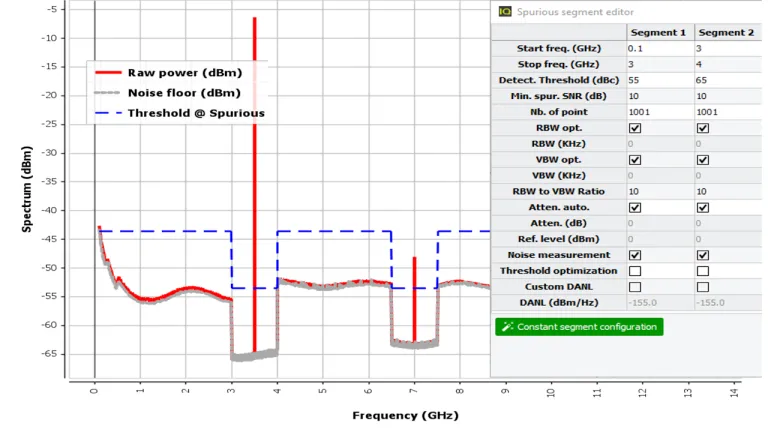
Quickly Detect Unwanted Tones
The Fast Spurious detection mode is provided with scalar or vector setups. It enables Spurious detection using a spectrum analyzer, or a VNA equipped with spectrum software options. This module allows a fast search and analysis of spurious signals, using the spectrum analyzer to recover the trace for each swept parameter.
A processing algorithm is then employed to dissociate spurious frequencies from signal frequencies. Detection-per-frequency segment is possible when different criteria based are needed for each band. Spurious detection is an important step in the Design Validation Testing (DVT) and the Production validation testing (PVT) of RF and Microwave power amplifiers. Spurious emissions decrease the system performance and cause interference in adjacent frequency bands. Some industries like aerospace and defense must detect very low-level spurs.
A classical technique consists of reducing the resolution bandwidth to the narrowest to lower the noise floor of the equipment. However, the implementation simplicity of this technique comes at the cost of a very long measurement time, especially since the spurious location cannot be predicted in advance, which imposes a full scan of a large frequency bandwidth at a very low RBW level. Even with new fast spectrum analyzers, spurious detection can take hours or even days when combined with nested loops of frequencies, biases, power levels, VSWR circles…
IVCAD IVT uses fast spectrum analyzers using FFT filters to search spurs and reduce testing time. The IVCAD IVT spurious research algorithm automates and speeds up the process.
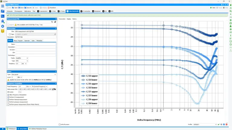
Can Your Amplifier Be Linearized Using its Video Bandwidth?
In addition to harmonic measurements, using two combined analog RF sources or one vector signal generator, a spectrum analyzer, or a vector network analyzer with frequency offset options, IVCAD IVT guides you through a simplified calibration procedure and provides high measurement accuracy needed for 2-tones measurements and Intermodulation (IMD) products.
IVCAD IVT handles independent or vector signal sources and balances the two tones levels for an accurate IMD characterization. A 3D nested sweep, including the carrier frequency, the power, and the spacing of the tones, can be performed to extract a complete IMD characterization of the Power Amplifier in one step.
Video Bandwidth (VBW) measurements represent a challenging measurement task. However, IVCAD IVT handles this measurement efficiently, setting the amplitude of the tones according to the target third-order intermodulation distortion (IMD3) value set by the user. Then, the software sweeps the spacing between the tones and adjusts the balance between them before recording the intermodulation— up to the ninth order. Taking advantage of the speed of VNA sweeps. This measurement takes just a few minutes.
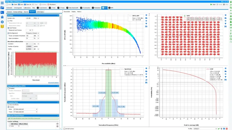
Take Control of IQ Data
Once the Video bandwidth of the power amplifier is known, IVCAD IVT can use IQ values sent to the Vector Signal Generator (VSG) and fetched from the Vector Signal Analyzer (VSA). The IQ data is resized, realigned, and analyzed to extract user-selected parameters (ACPR, CCDF, PAPR, Dynamic AMAM…). With this option, the VSA does not need any specific software options, the application aligns the IQ signals at the input and the output and extract all requested parameters.
The available measurements are:
- IQ Data
- EVM on Signal
- ACPR
- CCDF with Trace
- Dynamic AM/AM and AM/PM
- Instrument-based DPD
Based on the waveform generator provided with the Front-End module (IVF), IVCAD (IVT) integrates the IQ measurement interval selection tool to speed up the measurement process by identifying the most appropriate signal segment that is most representative of the original signal in terms of statistical characteristics. This feature is very useful when a compromise between measurement speed and accuracy is required. When instruments are equipped with DPD analysis options, the IQ module can control these options. It uses appropriate instrument drivers and improves the characterization of the power amplifier by verifying its linearizability.
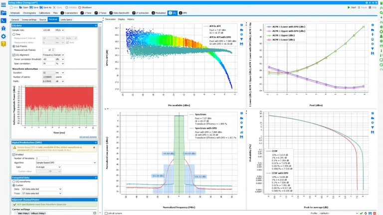
Demonstrate the Power Efficiency of Your Circuits Once Linearized
Power Amplifiers are inherently nonlinear components in a communication system and are the most critical components. The nonlinearity generates spectral regrowth, which leads to adjacent channel interference and violations of the out-of-band emission requirements. The nonlinearity also causes in-band distortion degrading the bit error rate (BER) performance.
It is possible to reduce the nonlinearity by backing off the power amplifier to work in the linear region. Still, this method is not viable because of the low efficiency of the power amplifier in this regime. Power amplifiers must be linearized using different techniques to enhance efficiency without compromising the linearity. IVCAD (IVT) introduces different DPD techniques and algorithms to verify that the Power amplifier potentialities to optimize both linearity and efficiency at the same time.
When different DPD techniques must be tested on the Power amplifier, IVCAD (IVT) offers different methods to linearize your circuits.
- Sample-based - This technique is an iterative measurement-based method that allows for achieving quasi-ideal linearization results for reference purposes. This method is used during the PA verification and development phase and cannot be implemented as a real-time DPD algorithm in a transmitter.
- Memoryless (M) - Memoryless models focus on the power amplifier with a memoryless nonlinearity: the current output depends only on the current input through a nonlinear mechanism. This instantaneous nonlinearity is usually characterized by the power amplifier’s AM/AM and AM/PM responses. The amplitude and phase deviation of the power amplifier output signal is given as functions of the amplitude of its current input.
- Memory Polynomial (MP) - The memory model is commonly used as the signal bandwidth gets wide and the power amplifiers exhibit memory effects, especially for high-power amplifiers used in wireless base stations. Consequently, the current output of the power amplifier depends on the current input and the past input values.
- Generalized Memory Polynomial (GMP) - This model is built by augmenting the Memory Polynomial model considering the cross-term order. The user can set this order.
- 3rd Party DPD algorithm - This option is a gateway to run a DPD algorithm developed by the user. This option also offers an Open-source MP algorithm that the user can adjust and optimize to his power amplifier under test.
IVCAD (IVT also runs instrument-based DPD. Some instruments with high data process capabilities can embed proprietary DPD algorithms that can be used for power amplifier linearization. DPD Control of algorithms hard-coded in FPGAs can be used to evaluate the circuit potentialities.
Also Discover
Unify Radio-Frequency measurement, modeling, and simulation workflows

Extract transistor models for circuit simulation and circuit models for system simulation

Waveguide measurement setups ctrl, Active Load Pull measurements, Data generation for advanced component and circuit modeling

Run Stability Analysis of MMIC Circuits, Perform System Simulation using behavioral models
Define RF signal testing models, start with basic measurements and create custom measurement or simulation scripts and templates for data analysis
Learn What SIMULIA Can Do for You
Speak with a SIMULIA expert to learn how our solutions enable seamless collaboration and sustainable innovation at organizations of every size.
Get Started
Courses and classes are available for students, academia, professionals and companies. Find the right SIMULIA training for you.
Get Help
Find information on software & hardware certification, software downloads, user documentation, support contact and services offering