Optimizing STL Files for 3D Printing
Discover how to optimize your STL files for 3D Printing
Introduction
STL, also known as STereoLithography or Standard Tessellation Language, files are one of the most popular file types for 3D printing solid models. An STL file takes the information about a 3D solid model created with a CAD software, such as SOLIDWORKS, and stores it for later usage or editing. After a 3D model is created, the designer will choose a file type to save the model as. An STL file is designated by the file extension “.stl”. This file type is compatible with many CAD softwares and can interface with many 3D printers and computer-aided analysis software.
How is an STL File Created?
The process to build an STL file first starts with the creation of the solid model by the CAD designer. Creating the solid model involves defining the component’s geometry and typically involves a combination of planes, extrusions, surfaces, and possibly strategic material removal.
When a designer chooses to save a solid model as an STL (Standard Tessellation Language) file, the surface of the object is encoded using a concept called tessellation, hence the meaning of the STL acronym. Tessellation is a simple concept whereby a surface is covered with a pattern of shapes so that there are no overlaps or gaps. Tessellations occur in the world around us commonly, examples include brick walls or tiled floors; they can be made from simple shapes or complex shapes.
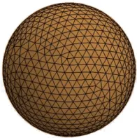
An STL file uses triangles to perform tessellations for conveying information about the surfaces of a 3D model. This method was discovered in 1987 by Chuck Hill. This discovery was made as part of the process of transferring information from the 3D CAD system file to the 3D printer file. It turned out that the tiny triangles, or facets, utilized to define the outer surface of the 3D model are perfect for defining simple and complex surfaces alike. More complex surfaces will require more triangles to define their surfaces, as they must be smaller to fit the curvature of each surface. For example, a simple cube will require 12 triangles whereas a sphere may require thousands of triangles.
Depending on the 3D CAD software utilized, there are settings that may be manipulated to change the size or complexity of the tessellation pattern so that the file size is smaller and/or the model is less complex. Consult with your printer manufacturer’s instructions to determine how to change settings that impact tessellation patterns. In addition, when 3D printing STL files, it is important to pay attention to the minimum feature thickness that a 3D printer or the 3D printer filament is capable of printing. Feature sizes less than this will not be correctly printed. Ensure that the tessellation size is appropriate for each application.
Dassault Systèmes provides a simple way to have your clear 3D printed parts expertly produced. Check out our website today to learn more about our innovative 3DEXPERIENCE® Make with on-demand access to industrial clear 3D printed parts service providers.
Optimize Your STL File for 3D Printing
If the end goal for 3D solid model creation is to 3D print the model, first the two methods for storing information about the triangular tessellations should be considered:
- Method One: ASCII encoding where the coordinates of the vertices of each triangle are stored. These 3D coordinates provide an exact location for each triangle, thereby saving the exact contours and locations of each surface.
- Method Two: Binary encoding whereby the components of the unit vector normal to each triangle are stored. This vector points outward from the surface, with respect to each triangle.
As one may be able to decipher, the ASCII method involves the storage of a large amount of data (3 sets of 3 coordinates for each triangle). The binary encoding method is much more compact. The method of tessellation should be chosen, based on solid model complexity and can be optimized to reduce printing time.
Here are some other general tips to ensure a 3D STL model is optimized for 3D printing;
- Ensure all walls have a thickness greater than zero as a zero wall thickness cannot be printed.
- Ensure all walls have faces necessary to define them.
- Perform STL resolution optimization prior to uploading the STL file to the printing software. In general, a smoother surface will result in a smoother 3D printed model. But, the smoothness is also limited by the layer thickness the printer and filament material are capable of producing.
- Try to decrease the complexity of the STL files. Larger file sizes will take more time to print and complex files may not end up producing the best results. This can be achieved by increasing the chordal and angular tolerance values.
- Remember that details which are smaller than the layer thickness will not be present on the 3D printed part.
- Skip the UV function, opting for XYZ coordinates instead.
- Use the merge function to combine two or more primitive shapes to reduce the complexity of the solid model.
- As a general rule of thumb, the smallest detail on any 3D printed part should be four times bigger than the layer height.
- Utilize the next section to fix common STL file errors prior to printing from an STL file.
Following the aforementioned tips should allow optimization of 3D print files to ensure the most accurate printing, within the smallest amount of time.
Resolve Common STL Errors
Although 3D modeling and STL file generation may seem straightforward, there are still a few common mistakes that are made in the design of CAD models, specifically STL files. These failures in the modeling step can result in failures in a 3D printed part, like missing faces, poor resolution or incorrect geometries, so it is important to catch them prior to starting the 3D printing process.
One of the most common failures with an STL file is a missing tessellation figure or a missing triangle. There are a host of rules that the tessellation pattern must follow, in order to accurately define the surfaces of a 3D solid model. One of these rules is that adjacent triangles must share two common vertices. If the two vertices are not shared, the result will be holes in the mesh of the solid model. This will result in printing an incomplete solid model. The gaps or holes may also occur on part edges. There are several software packages on the market that claim to repair the gap or hole issues or these can be remedied by fixing each issue individually.
Another issue that may arise due to the triangular tessellation data storage method is that the individual triangles may overlap or intersect improperly. This error will cause an unnecessarily long print time. These overlapping triangles need to be removed or unified.
If a binary encoding method is utilized to build the STL file and store the data, the direction of the normal vectors point is critical for the 3D printing process. If some of the normal vectors are pointing in the wrong direction, the 3D printer will not be able to correctly determine where the inside and outside surfaces of the part are and therefore will not be able to accurately slice and print the part.
The last problem which has been previously mentioned is an over-defined tessellation or a mesh with too many triangles. This typically happens with more complex shapes. While not an error that will result in an inaccurate print, this will result in an unnecessarily long print time. In addition, most of the time these small details will not be printed because an over-defined mesh tends to have triangles that are smaller in size than the layer thickness of the print.
Regardless of the issue encountered, the optimal resolution method is to correctly design or re-design the CAD file with the native CAD software before exporting the model as an STL. Ensure that a 3D printing file is correct before starting a print job. This will produce better results over utilizing repair software.
Get multiple quotes for your parts in seconds