Technical Drawing for CNC Machining
Technical drawings for CNC machining communicate a wealth of information about your part to the manufacturer. Learn how to prepare these drawings best here.
How to Best Prepare a Technical Drawing for CNC Machining
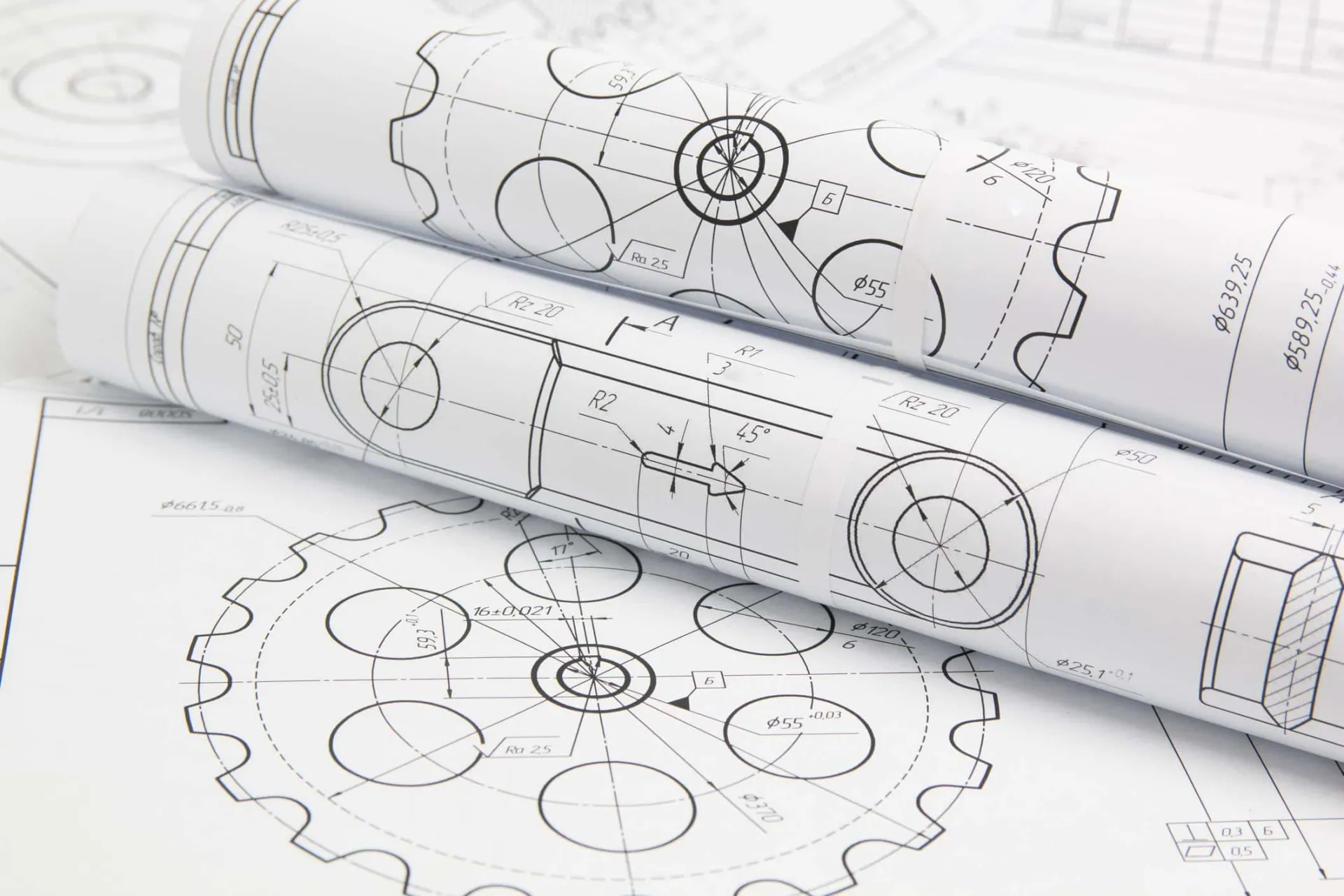
Technical drawings are documents providing highly detailed 2D drawings of your part. These mission-critical drawings allow for comprehensively communicating your part's requirements to the manufacturer.
When it comes to CNC machining, technical drawings are essential instructions that shed light on 3D models. In this article, we discuss the components of technical drawings, their importance, and step-by-step instructions for preparing technical drawings for your parts.

What is a Technical Drawing?
Technical drawings for CNC machining usually encompass a title block, coordinates, multiple views, and any pertinent notes for the manufacturer. Let's take a closer look at each of these components now.
Title Block
Located on the bottom right of the document, the title block provides basic information about the design. This basic information includes the name of the part, the names of the professionals who designed and approved the part, and the company's name.
The title block may also contain technical information including scale, angle of projection, system of measurement, surface finish instructions, and materials. The structure and format of the title block can be as customized as an engineer or designer prefer.
Coordinates
For larger parts or parts with complex features, coordinates are utilized along the borders of the drawing. These coordinates act as points of reference when communicating about the drawing.
Orthographic Views
Simply put, orthographic views provide the most important data about the geometry of your part. That's because orthographic views provide most of the tolerances and dimensions for your part's design. These views are 2D representations of your 3D part from multiple points of view.
Hidden lines might be utilized in orthographic views to describe key features that are not visible. For most parts, two or three orthographic views are sufficient for encompassing all the geometry.
Isometric View
Isometric views are 3D pictorials of your part. Even though an isometric view is not necessary for all parts, it's usually best to include this view because it allows the manufacturer to better understand the geometry of your part. Moreover, isometric views might also offer valuable data such as build orientation or installation direction.
Section Views
Section views are 2D depictions of slices through parts. These views describe the internal features of parts that are not encompassed in isometric and orthographic views. It's helpful to be aware that section views are typically positioned in line with orthographic views. Cutting lines are used on the orthographic view to indicate where the part is being cross-sectioned for the section view.
Detail Views
For orthographic views with areas that are hard to dimension, you can utilize detail views to call out those areas. You can put detailed views anywhere in your drawing. Detail views are indicated by a single letter showing what area of the orthographic view is being called out.
Pertinent Notes for the Manufacturer
It's recommended that engineers and designers take advantage of pertinent notes for the manufacturer. These notes are often found at the bottom left of the technical drawing or just above the title block. These notes cover any information that wasn't encompassed in the drawing such as special instructions for the surface finish.
Why are Technical Drawings Useful for CNC Machining?
Technical drawings are vital documents that are paired with 3D CAD files in the world of CNC machining. The importance of these technical documents can't be overstated as is evidenced in some of the important roles they play in the manufacturing process:
- Technical drawings describe features that can't be encompassed in a 3D CAD model. Examples of such features include external and internal threads.
- Dimensions, annotations, and tolerances give the manufacturer a comprehensive understanding of the requirements for fabricating the part.
- Part designers and engineers can provide instructions for special requirements such as surface roughness and finishing to the manufacturer.
What if your part design simply doesn't have any complex features or special requirements? We still highly recommend that you include technical drawings with your 3D model because the manufacturer will no doubt refer to them during the manufacturing process.
How to Prepare a Technical Drawing for CNC Machining
While there is no one-size-fits-all process for preparing a technical drawing for CNC machining, here are the basic steps to follow to ensure your drawings are the best that they can be:
- Step 1. Determine the most important views for your part and put orthographic views in the center of the drawing. Be sure to leave ample space between orthographic views in order to add dimensions.
- Step 2. Does your part have intricate features or other areas that are hard to dimension? If so, add detail views or section views.
- Step 3. Now, add construction lines to all of the views. This includes centerlines for defining planes or axes of symmetry, center marks, and center mark patterns for defining the location of hole centers or of circular patterns.
- Step 4. Once construction lines have been added, you're ready to add dimensions to your drawing. We recommend starting with the most critical dimensions first.
- Step 5. Next, detail the location, length, and size of all threads.
- Step 6. For any features requiring a higher degree of accuracy than standard tolerances, add additional tolerance information.
- Step 7. Complete the information in the title block and ensure that special instructions such as surface finish and deburring instructions are included in the pertinent notes for the manufacturer section.
Summary: Technical Drawing for CNC Machining
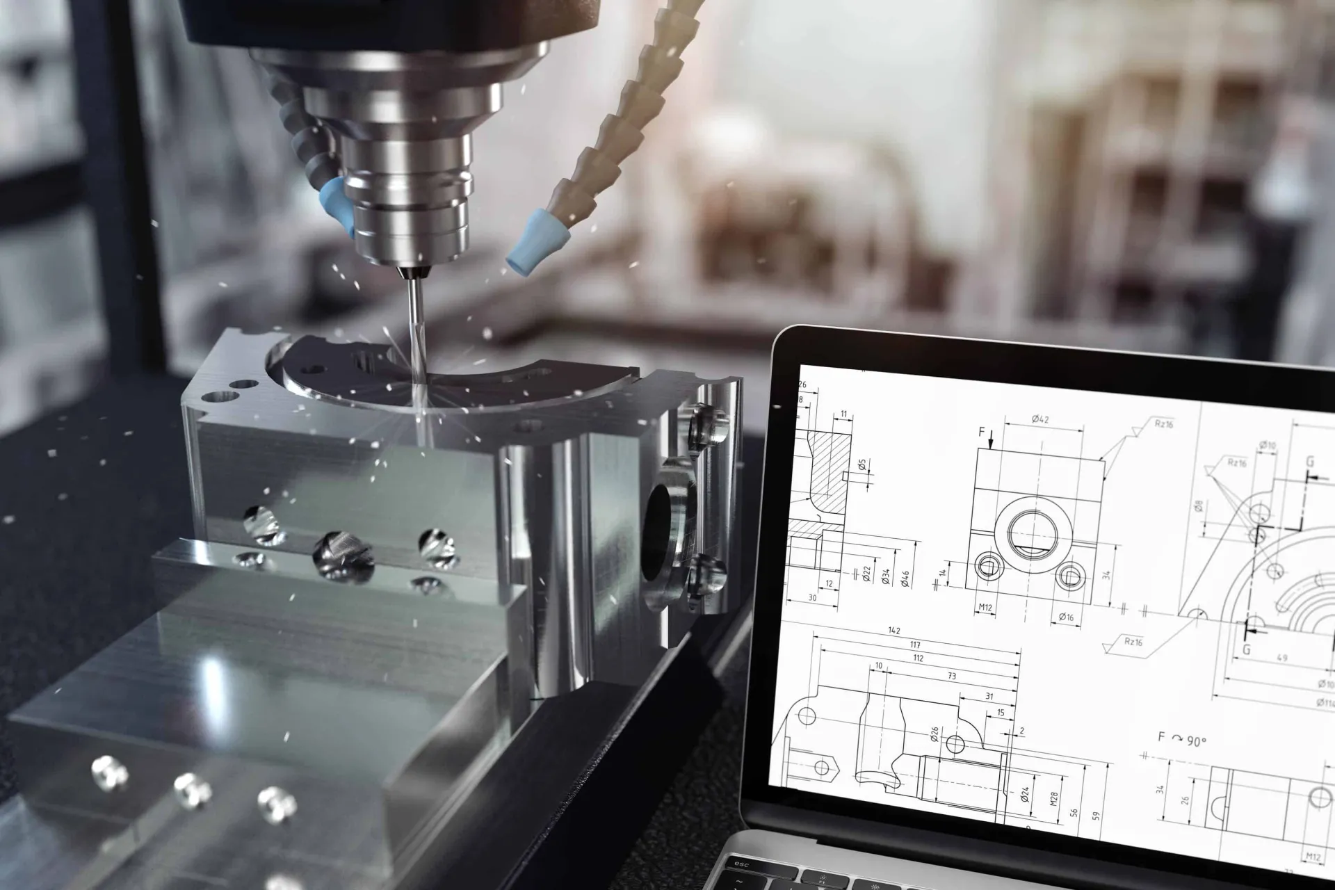
In today's CNC machining environment, the manufacturing process usually begins with a 3D CAD model generated by specialized software. With the help of CAM software, the 3D model is translated into G-code, which is a CNC machine language. Once programmed, the CNC machine produces the part using subtractive methods.
There's no denying that 3D CAD files contain a wealth of critical data for CNC machines. That being said, a 3D CAD file does not negate the incredible utility of technical drawings. Technical drawings are the bedrock for communicating designs to manufacturers, and this fact will remain to ensure your part is made just as you intended.
Get multiple quotes for your parts in seconds