Reduce cost of CNC Machining
So you want to know how to reduce the cost of CNC machined parts?
Introduction: Easy = cheap
So you want to know how to reduce the cost of CNC machined parts?
It is easy. Design it according to the manufacturing process rules and limitations. Period.
Not clear enough? OK then…
The cost drivers of CNC machining are
- Machine usage
- Material usage
Both are driven by your design. Reduce those, and you reduce the cost. Period.
Not clear enough. OK then…
What is easy to make is cheap to make, so design your part easy to manufacture, and it will be cheap.
Your design represents the major element of the cost in manufacturing. This is the only variable of the equation you can influence. I will describe cost drivers below so you can learn how to reduce it of your CNC milled part straight from the drawing board. Improving each of these attributes (and there are many) will make your part cheaper to produce and make the machine operator love you. But, first, if you ask this question, we should start by redefining what CNC Machining is. It will help to understand the rest better.
Discover SOLIDWORKS 3DEXPERIENCE for Makers

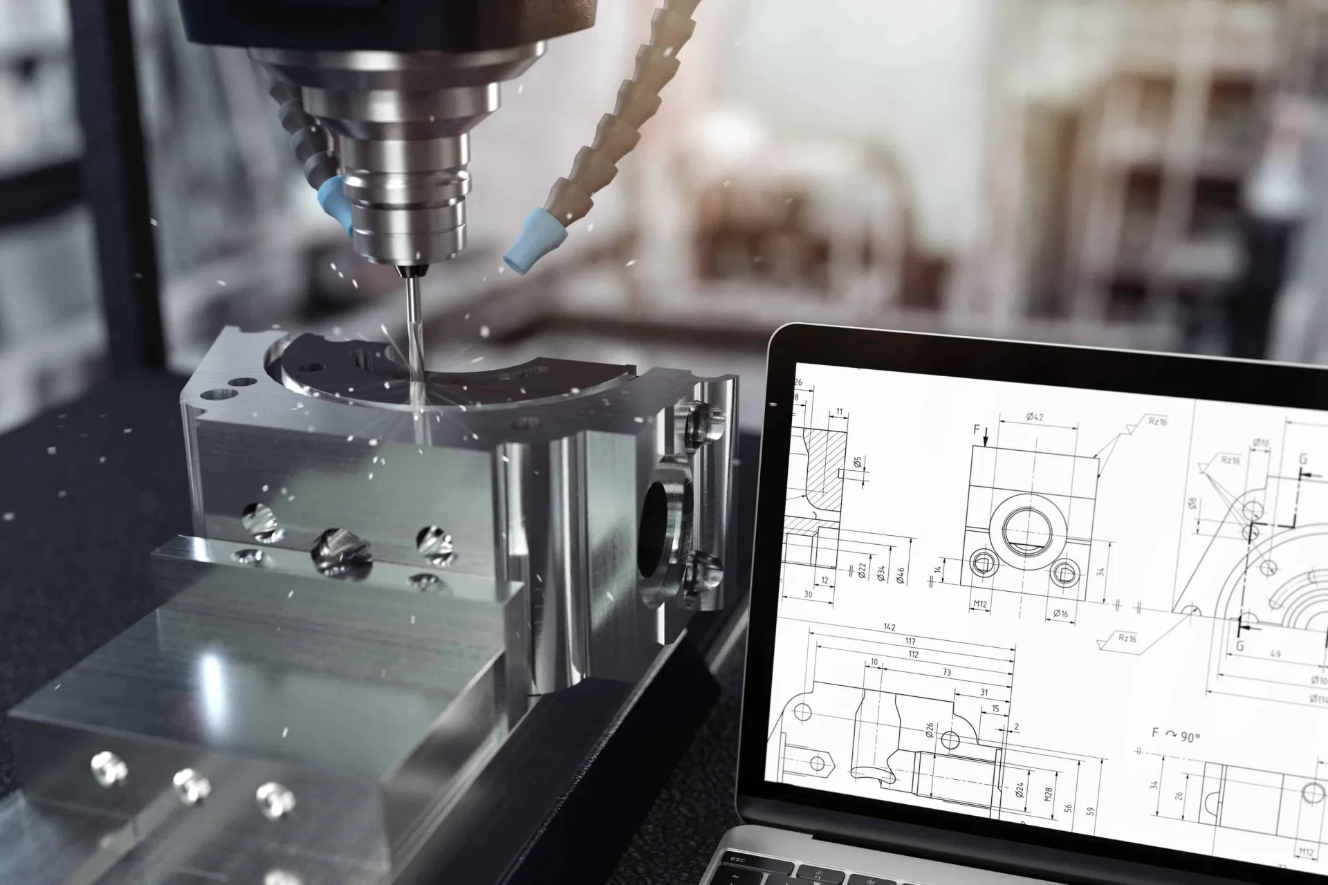
What is CNC Machining anyway?
A SUBSTRACTIVE process
CNC machining is a substractive manufacturing process as opposed to an additive process.
- It means that you make a thing by REMOVING material from a solid block. In that sense, it is like Carving a stone.
- Drilling a hole in a wall
- Digging a tunnel in the ground
- Taking bits of tiramisu with a spoon
You remove material.
In an ADDITIVE process, you will ADD things like a construction worker building a wall out of bricks.
To do a SUBSTRACTIVE job, you need three things
- Some raw unshaped material. This is called a BLANK
- A thing harder than the BLANK to help you remove material. This is named the TOOL
- Something to either move the tool TO the material or the material TO the tool.

A bit of lexicon
Going back to CNC,
For CNC Milling, the tool is a rotating cutter. A robot arm moves around this rotating cutter. When the rotating cutter meets the fixed blank, it removes material from the blank. Easy, isn’t it?
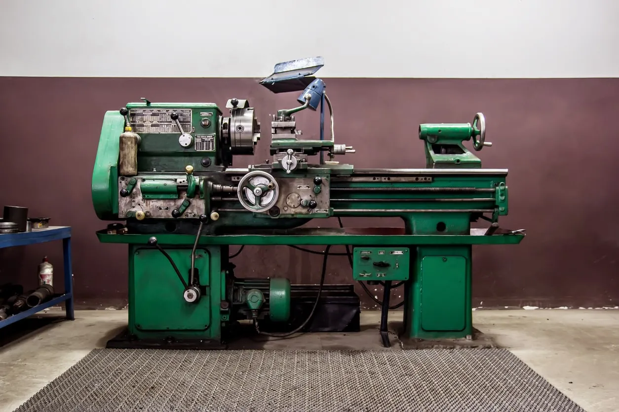
For CNC Turning, the tool is a fixed cutter moved around by a robot arm, and the blank will be spinning on an axis. When the fixed cutter meets the spinning blank, it removes material. Easy as well.
Sadly, not all robots are created equal.
The robot arm can move either in
- Two dimensions (X and Y)
- Three dimensions (X Y Z)
- Three dimensions plus multiple rotation axes of the blank plate or the robot arm holding the tool (called 4/5/6 axis CNC milling center).
These dimensions are called the MILLING AXIS. The robot will move the cutter following a given path. It is named the TOOLPATH. Software create the toolpath, how? They will analyze your design and calculate the quickest path with the available tools.
The tools available are known as the TOOL LIBRARY or TOOL SET. Tools are of various sizes and shapes. As our target is to remove material, the smaller the tool, the longer it takes, and the longer it takes, the more expensive it is. Think about digging a hole with a spoon rather than a shovel, or coloring on a wall with a crayon rather than a large brush.
We now know what are, BLANKS, TOOLS, TOOLPATH, TOOL SET, and MILLING AXIS. Remember these words. They will be important later.
Now what?
Process limitations
The robot will do its best to remove the material needed to manufacture your part, but sometimes, it will not be able to reach some areas because
- It doesn’t have enough axis
- The tool is inappropriate (too big, not long enough…)
- The robot arm maneuvering the tool is not flexible/slim/long enough
A real-life example of tools unable to reach some areas are
- Your hand into the peanut butter jar because it is too big.
- Your arm is not bending in enough places to go up a convoluted air duct.
- Your fingers are not grabbing your credit card, which felt under your car seat because it is too far.
CNC robots have the same kind of issues. Bear with them. For instance, no cutter will be able to drill a 1 mm diameter, 1-meter deep hole. Picture it in your mind for a second. It is too deep and narrow.
Similarly, a CNC robot arm with 2 “elbows,” a total length of 1 meter, and a diameter of 20 cm will never manage to go remove material at the bottom of a 10 m bendy 10 cm diameter rabbit hole.
Now you ask, why am I saying all this?
Because you cannot make a part easy to manufacture (remember easy = cheap) if you do not understand the pros and cons as well as the limitations of the machine.

Exercise yourself
We, humans, learn things by doing them and mimicking people. This is the same for becoming good at reducing CNC costs. Going through these exercises, even only mentally, will help you on your quest to shave some cents of your manufacturing costs.
Thou Shalt Be a CNC Robot
As a beginner on this subject, it can sometimes be hard to understand what is feasible or not by a CNC mill. In order to picture better what is easy or not to CNC, you can do the following exercise:
- Make a mockup of your part (of cardboard or foam, for instance) or design it with a 3D CAD Software (As SOLIDWORKS or CATIA).
- Make a little box in which your model fit,
- Take three pencils of different diameters, a fat, a medium and a small one.
- Grab one of them with your hand and imagine your arm is the robot arm., while the tip of the pencil is the cutting element of the tool. You can now only move the tool in a limited number of axis. (Remember X Y Z and more, see above.)
- Put the model in the box. The box is the blank of raw material you need to machine to get your final design. The box is fixed to the table. You cannot move it.
- Now drive your pencils around, one axis at a time, and imagine it removes material as it passes across the box/blank. First up and down, then left and right, then up and down and so on….
Which strategy will you use to delete all the material needed to go from the blank to your finished design?
The goal is to utilize as few axis and tools as possible and the largest tool as possible at first.
Why few axes? Because a 5-axis milling machine costs more than a 3-axis milling machine.
Why few tools? Because changing a tool takes time, even if it is done automatically by the machine.
Why larger tools? Because using large tools means you remove more material per minute. Also, smaller tools tend to break more easily.
Why not move the blank from the table? Because if you do it, so the operator or the machine will have to do it. It will take time and/or a more complex machine. Also, by touching the reference plan, you can create alignment errors — (more on this later with tolerancing).
And so on….
You cannot think of a way of doing it. It is likely your part will be hard to CNC. Knowing this, now redesign your part, so it still fulfills the same goal but is accessible to CNC. If it remains impossible, make it in two, three, or more parts.
A blank slate
Another interesting exercise is to design a part from a blank in a truly SUBSTRACTIVE manner.
Generally speaking, in a CAD environment, designers try to start from nothing and add material where it is necessary. This is a typical ADDITIVE mindset, which tends to be more natural for us. Historically, our ancestors combined natural “objects” (a rock, a branch, some mud) to make more complex objects.

The SUBSTRACTIVE way of designing things is less natural to us. This is why it is essential to exercise our minds to do it.
In your CAD environment, or for real (with wood, foam of clay), create a blank (a raw brick of material). Then start removing material from it with a fixed number of tools, and try to achieve your design goal this way. Suddenly, it becomes clearer how the machine will operate to turn a blank into a part.
During this process, think about how the part will be clamped in the CNC machine. Is this feature reachable? Is it necessary to delete this bit of material to accomplish your functional goal?
Finally, yet importantly, you can add to this exercise the fact that you could remove material in the order you wish the CNC machine would do in the CAD software. Every milling phase will therefore be an operation of your design tree. For instance: First leveling and squaring the visible faces of the blank, then creating a large pocket, then drilling holes, and so on….
During this process, try to think about which tool you will use at each step and how many axes will be necessary to complete the job.
I am the operator
Another fun exercise is to put yourself in the operator’s position or the person making the quotes.
Version 1) Go on the web and search pictures of CNCed milled brackets. Collect them, and replicate the part in your CAD software if you have the time. Then analyzes how you would manufacture these if someone questioned you to make them at the lowest-cost possible.
Version 2) Ask a CNC geek friend like yourself to be the “designer” and provide you with a design to be CNC machined.
Then create your own quotation system. What blank do you start? How many operations or cutters are required? What are the small/complicated/risky features that may lead to a defect? If defects happen, how would you cost them? And so on.
Finally, yet importantly, propose design changes to reduce the cost. This can conduct to exciting discussions with the colleague who designed the part and sometimes shift the entire design paradigm of an assembly. Suddenly, by doing this job, you will realize how each feature is unique, leading to a drastic price increase. Oppositely, a simple design could almost be the sum of the cost of the blank, adding a few minutes of a simple machine time using standard cutters. You understand now through these exercises than every single factor of your design will influence the cost of manufacturing.
Now that you have gone through the thinking process, let me list the most obvious price drivers.
Major CNC cost driver list:
Material related cost drivers
Material selection:
This one seems obvious but has more externalities than expected. A rare material with advanced properties is, of course, more expensive. However, a HARD material is HARD to CNC and will require more advanced tools to be cut (remember, the tool needs to be harder than the blank). This will lead to a cost increase.
Solution: always take the softest and most common material required for the job.
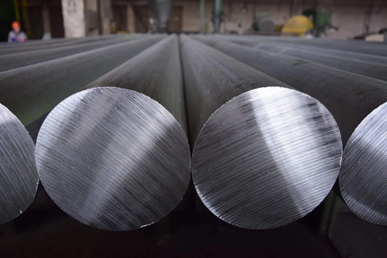
Blank size
Your starting point is a block of raw material (a blank). Blanks come in standardized sizes. Design your part to fit in a standard blank of the selected material. If your part is larger than the blank, the operator will begin with a larger blank, potentially leading to a LOT more material to be removed. Remember that, usually, a side of the blank cannot be the side of your part. You need to delete 3 to 5 mm to the raw blank dimension.
Solution: Check in which standard blank your design fits in. If it doesn’t fit, think about splitting your part in two.
Machine-related cost drivers
Startup costs
Once the operator receives your part, he needs to generate the toolpath, get some raw material, book the machine, make a quote, a manufacturing order… There is a TON of things to do before making your part. Nothing is free, and startup costs will cover all the work done prior to the manufacturing start.
Solution: order a larger quantity to mutualize startup cost across a larger batch.
Number of axes required
CNC machines come in all sizes and shapes, but a good rule of thumb is that the more complex, the more expensive. Therefore, by reducing the number of axes required to mill your part, you will decrease the manufacturing cost simply because the price per minute of this machine will be lower. Also, less advanced machines tend to be more common and have been here for long. There is more competition and less hurry to pay back the loan taken to purchase, thus driving costs down.
Solution: design simple parts. If you cannot do it, split them into several pieces and assemble them afterward.
Number of Operations Required
The vague word “operation” lies in what the machine cannot do automatically. This could be either
- moving your part manually within the machine to allow the milling of a specific design feature
- setting up a particular tool that is not an element of the regular toolset
- having to switch your piece to another machine to make one specific feature.
Operations take time and can also generate mistakes such as inaccurate tolerances. These mistakes make parts rejects. So the manufacturer will tend to charge more in case mistakes happen during multi-operation processes.
Solution: design part to manufacture it in one single operation in a single machine. If you cannot do it, split your part in two, making each piece manufacturable in a single process.
Tools used
CNC milling machines have toolsets fixed in number. The oldest/smallest machine will only have one single tool like the manual lathe I learned “milling 101” on at university. Modern one will have turrets with a dozen or more tools on them. The robot arm comes and gets the required tool for the job on the turret.
However, the toolset tends to be standard and limited in size. If you need too many tools or some odd tool for your job, the operator has to install the tools in the machine and reprogram it. Thanks to that, he would know if the turret slot number XYZ could contain your very exotic tools. Maybe he would also have to order this very tool for you.
This is long, complex, and usually unnecessary if you think through your design well enough.
Solution: learn what standard tools are and try to stick to them. Focus on the depth to diameter ratio as small tools that allow the most refined cuts to be the shortest.
Diameter of the Tool Used
Similarly, where time is money and small tools are fragile, try to use large tools (i.e., this also means focusing on designing large features) whenever possible and within the dimensions of regular large tools. This asks a bit of research and may not be relevant for a single part. But when it comes to mass manufacturing, this can make a huge difference as all the small elements add up quickly and may kill your productivity, maintenance/downtime, and reject rate.
Design-related cost drivers
Only remove what is necessary
As stated above, CNC milling is a SUBSTRACTIVE process. Its cost depends on the amount of material you remove from a blank. Try then to fulfill your design goal by deleting as little material as possible. Suppose weight and accessibility are not a concern and your design goal is fulfilled. In that case, there is literally no reason to remove any more material from the blank than what is strictly necessary. As most designers think in an ADDITIVE fashion, this will lead to surprising design results but will drastically improve your manufacturing cost.
Solution: Start from the blank and only remove what is needed to fulfill your goal.
Freeform VS. regular form:
Convex corners
There is no cutter to cut a convex corner directly. This means the milling machine needs to go through a LOT of tiny paths to create the impression of a convex corner. I say “impression” because unless you smooth it in a second operation, the CNC mill will always make even a fine, stairs-like pattern on such features. Alternatively, a CNC operator can make a bevel in a single procedure
Rounded internal pocket corners.
Like with convex corners, there is no cuter that can cut a perfectly square pocket corner in one operation. Because the cutter is rotating, and when a shape turns, its rotation radius is round, not square. Therefore the easiest is to leave the radius equal to the diameter of the tool, which will cut the pocket. This depends on its size.
Small/fragile features:
The rotating cutter is rotating fast, like really, really fast. Because of this, it can shear small, fragile elements, especially if these are not connected to anything. It is still possible to mill tiny features, but it will take a smaller cutter and a lot finer milling path. If the feature breaks, all the parts need to be redone, increasing the over cost.
Clamping Face
I don’t know if you noticed, but it is harder to grab an organic-shaped object than a regular-shaped one firmly. If you design a part with very few regular shapes, it will be tough to clamp it into the machine. Specific clamps will likely have to be milled to clamp your piece in the machine (this topic is called jig and fixture design).
This can make sense if you are making twenty thousand parts. It does not make any financial sense if you are making three.
Solution: Work as much as possible with regular shapes with features easy to be made with standard cutters.
Odd features
Hole diameters/Hole depth
When you go to the DIY shop, you’ll notice drill bits come in standard diameter and length. Guess what? It is the same for CNC cutters. So if you ask for a 12.724896 mm hole in diameter, don’t expect the operator to find a 12.724896 mm tool that will nicely drill this hole in one go. First, the tolerance of the machine won’t allow reaching this level of tolerancing (more on this later). Second, it will likely have to drill a 12 mm hole. Then, it may push a cutter down that hole to rectify it to this odd measurement. This is becoming even more complicated if your hole is very deep.
In a nutshell, simply stick to standard diameter and diameter to length ratio. It will help everybody.
Odd threads
In the continuity of odd holes, dimensions come odd threads. Specific cutters will cut a thread inside a hole in one operation. This is simple, fast, and precise. It is another story of you asking for a custom thread. A cutter will likely have to be explicitly made altogether for the operation.
Needless to say, the price will also become very special.
Unreachable areas
In the same vein as the previous paragraph regarding tool accessibility, try to make each feature accessible to the cutter, considering its standard diameter and length. It will always be cheaper to reassemble two parts easy to manufacture rather than making a very complex one.
Tolerance
Like in life, within the CNC milling world, nothing is perfect. A part will never be exactly the size you specified on your technical drawing.
Tolerances are the deviation that the designer considers acceptable without compromising the functionality of the part manufactured. Does this radius need to be 10 mm, 10.1 mm, 10.11 m, 10.1111mm? Will it be a problem it is 10.12 mm or 9.999mm?
It is up to you to decide but keep in mind the more precise, the more complex and, therefore, the more expensive. There is a tolerance standard for CNC milling (ISO 2768, for instance). If you do not provide any specific information, the operator will consider that the tolerances you want are related to the norms in vigor in your local area. These apply to feature dimensions but also dimensions between features—space between two holes, for instance, or the concentricity of several holes.
If you have a very particular need for a finer tolerance, specify it clearly but make sure it serves a real purpose because it may skyrocket the price of the part. On the opposite side, if very loose tolerances are acceptable (looser than the standard you work in), you may also specify it. So the operator will not reject a part at the quality control stage based on this variable.
Surface Finish
Finally, yet importantly is surface finish. The surface finish is the aspect of the surface of a given face of the part. It can be raw from the foundry or the blank cut up to a mirror polish and anything between.
Surfaces can be serrated, sanded, bead blasted, polished, painted, coated, and so on. In the context of CNC milling, usually, the surfaced will be left raw from the last tool path that milled the surface. It means that you may see or feel with your finger tool marks. The rougher the surface finish is, the cheapest: the smoother, the more expensive.
Specify what is necessary according to your need with a preference for rougher finished on unnecessary faces to keep the price low.
Get multiple quotes for your parts in seconds