CNC Milling Finishing and Design Guidelines
Planning your next part production project? Make sure you know the CNC milling finishing and design guidelines that should be taken into consideration.
Introduction to CNC Milling Finishing and Design Guidelines
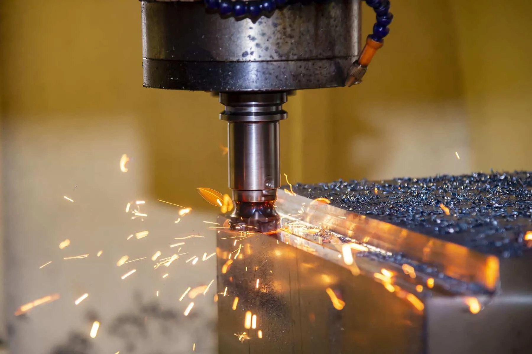
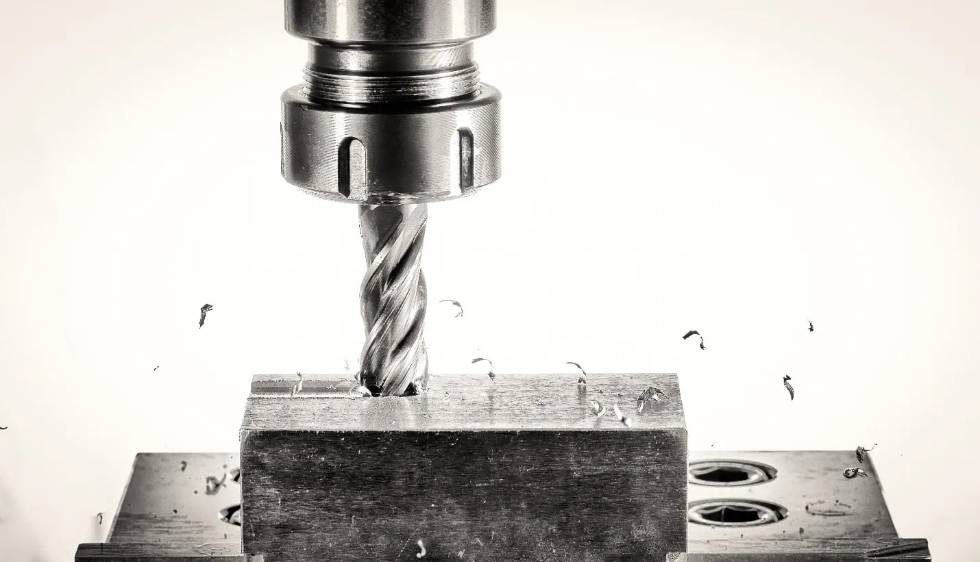
CNC milling is a machining process that removes material from raw stock to realize the final intended design. CNC milling utilizes round cutters that chip away material laterally. In 3-axis CNC milling, the workpiece is secured in place as the tool spins and moves up and down while removing material. Additionally, the bed of the 3-axis CNC milling machine then moves back to front and side to side.
Since CNC milling is a form of subtractive manufacturing, tool marks will be seen on your part when it comes off the machine. The good news is that several different finishing methods can be employed to increase the smoothness, wear, and corrosion resistance and aesthetics of CNC milled parts.
In this article, we take a closer look at several key CNC milling design guidelines, as well as the most common CNC milling finishing options that you need to be aware of as you begin to plan your next parts production project.
CNC Milling Design Guidelines
Make Sure Features are Compatible with Common CNC Milling Tools
As you begin to consider the design for your part, it's beneficial to know what tools are most commonly used in CNC milling. Ideally, you want to design features and geometries in your part that are compatible with standard milling tools. This is because you can decrease your overall lead time and cost. After all, the manufacturer won't need to spend their money and time making or procuring custom milling tools.
Avoid Sharp Internal Corners
CNC milling utilizes round tools. As a result, sharp internal corners must be left out of your part designs. Moreover, radiused corners need to be larger than the cutting tool. In fact, the radius of the corner will be half the diameter of the cutting tool. Additionally, it's essential to keep in mind that fillets are utilized when a sloped or drafted surface joins a sharp edge or vertical wall.
Try to Keep Narrow, Deep Slots Out of Your Design
When designing your part, remember that the final depth of an endmill cut must not be greater than 5 times the diameter for steel, 10 times the diameter for aluminum, and 15 times the diameter for plastics. This is because long tools can vibrate and become unstable during machining, which creates surface finishes with lots of tool marks. As an alternative, try increasing the diameter of the cutting tool (which may dictate increasing the width of the feature) or decreasing the depth of the feature or slot. Additionally, if the manufacturer can access the feature from two directions, this could reduce the length of the tool. However, doing so will involve additional setup, which adds to your project's lead time and cost.
Use the Largest Internal Radii Possible
One of the best ways to reduce the cost of your project and speed up your lead time is to design your part to be compatible with the largest internal radii possible. The reason for this is the larger the cutter is, the more material that can be removed in one operation resulting in less tooling and shorter lead times. As a general rule of thumb, try to make sure your radii are at least 0.8 mm where possible in your part design. Additionally, design fillets in your part to be a little larger than the endmill radius. Doing this will create a smoother path for the mill, which gives your part a better surface finish.
Ensure Proper Wall Thickness
Ensure your wall thickness is greater than 0.50 mm for plastic material and 0.25 mm for metals. The reason for this is that too thin walls are hard to machine because they present problems when it comes to maintaining tolerances and stiffness. Moreover, if the manufacturer removes too much material, the walls of your part could become too thin, resulting in warping and/or compromised tolerances.
CNC Milling Finishing Options
The Simplicity of "As Machined" Finishes
Using CNC milling for many parts and prototype designers, an "as machined" finish is more than sufficient for their needs. With an as-machined finished, the cutting tool might do an additional finishing pass to reduce roughness, or the part may just be accepted as is without a finishing pass and with tool marks showing. Standard as machined surface roughness is generally 3.2 μm. If a finishing cutting pass is made, the surface roughness may decrease to 1.6, 0.8, or even 0.4 μm. Finishing passes on CNC milling obviously increase the cost of production because of the extra steps involved.
In addition to making a finishing pass with the CNC milling cutting tool, as machined parts can be further polished and smoothed if desired, but doing so will remove some surface material, which could affect the final tolerances of your part. Nonetheless, as machined finishes generally provide the tightest tolerances of any finishing process for CNC milling.
Bead Blasting Provides an Even Smoother Finish
Some part designers desire a more refined surface finish for their parts beyond an as-machined finish. Bead blasting is an option for these designers because it provides a smooth satin or matte finish, and it also removes the tool marks.
In the bead blasting process small glass beads are forced against the part's surface under high air pressure. The resulting forceful contact from the beads removes surface material, which results in a smoother finish. It's essential to keep in mind that if your part has any features with critical tolerances such as holes, you can mask those during bead blasting to prevent your dimensions from being altered.
Powder Coating Provides Extra Protection
Powder coating is another finishing option for CNC milled parts. During this finishing process, a thin layer of polymer is applied to the part to protect its surface. This polymer layer is durable and corrosion-resistant, which helps protect the part from wear and tear. One of the benefits of powder coating is that it can fit to any metal material. Moreover, bead blasting can be used in combination with powder coating to achieve smooth surface finishes.
The method used in the powder coating process is much like spray painting, except dry powder is sprayed instead of liquid paint. To begin the powder coating process, the part is often primed to enhance corrosion resistance. Once primed, an electrostatic sprayer coats the part with dry powder. Finally, the part is cured in a high-temperature oven. Similar to Type II anodizing, powder coating can be necessary to achieve a variety of colors for aesthetic purposes.
Type II and Type III Anodizing for Protection and Aesthetics
Another CNC milling finishing option for parts is anodizing. Anodizing creates a thin ceramic surface layer that provides protection from wear and corrosion. The resulting coating is very durable, does not conduct electricity, and can take the form of many different colors for aesthetic purposes. Designers and engineers must know that anodizing can only be done on aluminum and titanium alloys.
In the anodizing process, the part is dipped in a sulfuric acid solution, and an electric charge runs between the component and the cathode. The resulting electrochemical reaction converts the part's surface into hardened titanium or aluminum oxide. Masking can be done beforehand to cover tolerance-sensitive or electrically conductive areas of your part so that dimensional accuracy isn't compromised and those areas can still conduct electricity after anodizing.
Anodizing takes two forms: Type II or Type III. Here is an overview of each type:
- Type II anodizing—commonly called "decorative" anodizing—can produce coatings with a thickness of up to 25 μm. This form of anodizing produces parts with a smooth surface in various colors while still ensuring good corrosion resistance.
- Type III anodizing—commonly called "hard coat" anodizing—can produce coatings up to 125 μm thick. This form of anodizing provides excellent wear and corrosion resistance. This superior durability makes these coatings great for functional applications.
Get multiple quotes for your parts in seconds