Bending Sheet Metals: The Basics
Sheet metal bending is a highly effective process for producing parts. Learn more about sheet metal bending today!
Introduction to Bending Sheet Metals
Sheet metal bending is an excellent method for creating a wide variety of parts. Bending methods can be very efficient for making new parts because the processes are relatively simple to carry out. Sheet metal bending utilizes external forces to modify the shape of the metal sheet. Sheet metal’s malleability enables it to be formed into a wide range of bends and shapes.
Bending sheet metals is one of the most common practices in metal processing worldwide. While there are many variables that must be addressed when planning a sheet metal part design, there are some standard bending methods that are important to be aware of to ensure your next sheet metal fabrication project produces its intended result. In this article we explain the most common sheet metal bending methods, discuss what bend allowance and K-factor mean, and review several very important design tips for sheet metal bending.

Discover SOLIDWORKS 3DEXPERIENCE for Makers
Bending Methods
The purpose of sheet metal bending methods is to shape sheet metal into its intended forms. Multiple factors play a role in deciding which sheet metal bending method is optimal for a given project. These factors include the thickness of the sheet metal, the bend radius, the overall size of the bend, and the desired use.
To better understand which sheet metal bending method is right for your purposes, here are explanations of some of the most common ones:
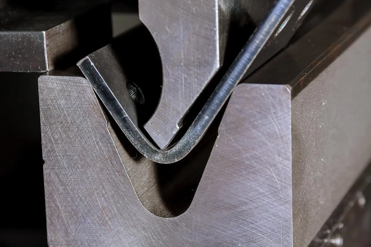
V-Bending:
This method is very common and is utilized for most bending needs. The method uses a “punch” and “V-die” to bend the sheet metal to specified angles. In this process the punch applies force on the sheet metal at the location over the V-die. As a result of the force from the punch an angle is formed in the sheet metal. The V-bending method is relatively efficient because it can be utilized for bending steel plates without having to change their position.
There are three common types of V-bending:
Bottoming
Bottom bending—commonly called “bottoming”—compresses the sheet metal to the bottom of the die to create the desired shape and angle. The shape and position of the die angle determine the final shape of the bend. One of the advantages of bottoming is that spring back (discussed later in this article) of the compressed sheet metal is not possible. The reason is that the powerful force of the punch coupled with the die’s angle causes a permanent conformity in the final structure of the sheet metal.
Coining
Coining is a type of V-bending that is desirable because of its precision and ability to distinguish between sheets. Like bottoming, in coining there is also no spring back of the sheet metal.
Air Bending
Air bending—also called partial bending—is not as accurate as coining or bottoming. Air bending is typically used when a simpler solution is needed because it doesn’t require the use of tools. One of the major drawbacks to air bending is that springback can occur. With air bending, the punch applies force on the sheet metal, which rests on each side of the die’s opening. A press brake is commonly used in air bending because the sheet metal does not have contact with the bottom of the die.
Roll Bending
Rolls bending is a great option for producing curved shapes or rolls in the sheet metal. Roll bending utilizes a press brake, a hydraulic press, and three sets of rollers to create different types of bends. As a result, roll bending is often used for making tubes, cones, and even hollow shapes because it uses the distance between its rollers to produce curves and bends.
U-Bending
U-bending is conceptually very similar to V-bending. The difference is that this method produces a U-shape in the sheet metal instead of a V shape. Like V-bending, U-bending is also very commonly employed.
Wipe Bending
Wipe bending is a method commonly used to bend the edges of the sheet metal. In this method, the sheet metal is placed on a wipe die and held there by a pressure pad. A punch then applies force on the edge of the sheet metal to produce the resulting bend. The wipe die is vital because it determines the inner radius of the bend.
Rotary Bending
Rotary bending is advantageous because it doesn’t cause scratches on the sheet metal surface like wipe bending and V-bending do. Moreover, rotary bending is beneficial because it can bend the sheet metal into sharp corners.
Bending Springback
One of the most crucial factors that can play a role in some of the sheet metal bending methods is springing back. When not properly managed, sheet metal can “spring back” to its original form after bending. For this reason, springback must be taken into account by bending the sheet metal slightly past the intended position or angle.
Bend Allowance and K-Factor
The bend allowance describes the adjustment that’s made to account for the tendency of sheet metal to bend back to its original form. As sheet metal is bent from its original form, its dimensions are altered. The force that’s applied to bend the sheet metal causes it to stretch and compress inside and outside. This alters the overall length of the sheet metal because of the applied pressure and stretching at the bend area. However, the length measured from the thickness of the bend between the exterior and the inner compressed surface under tension stays constant. This is represented as a line commonly referred to as the neutral axis.
The bend allowance accounts for the angle of the bend, the thickness of the sheet metal, the specific bend method, and the K-factor (a constant used in bending calculations, which allows for the estimation of the amount of stretch in the sheet metal). It’s a ratio of compression on the bend’s inside line to the tension outside the bend. As the inner surface of the sheet metal contracts, the exterior expands and the K-factor remains constant. The K-factor is typically between 0.25-0.5. It helps determine the specific type of materials required before trimming begins and it’s also utilized in the bend radius chart.
Sheet Metal Design Tips for Bending
When planning the bend of your sheet metal, there are several important design tips to keep in mind if you want to avoid experiencing a deformity in your sheet metal bends:
Uniform Wall Thickness
It’s imperative that your part designs have a uniform wall thickness throughout.
Slot and Hole Clearances
The space between any holes and the bend must be a minimum of 2.5 times the sheet metal thickness. For slots, more spacing is required. Slots need to be spaced a minimum of 4 times the sheet metal thickness from the edges of the bend. The reason for this spacing is that holes and slots will become deformed if they are located too close to a bend. Additionally, holes and slots should be spaced a minimum of 2 times the material thickness from the edge of the part if you want to avoid bulging.
Bend Radius
Bend radii are required to be at least equal to the thickness of the sheet metal. This requirement will prevent your sheet metal part from becoming deformed or even breaking. Additionally, you should keep your bend radii consistent to reduce costs. Moreover, all bends in one plane should be designed in the same direction in order to avoid part reorientation. Avoiding part reorientation will lower costs and reduce lead times for your project. One important factor to note is that you should avoid designing small bends in very thick parts because they are prone to inaccuracy.
Curls
One important rule of thumb is that the outside radius of curls needs to be a minimum of twice the thickness of the sheet metal. Moreover, the spacing of holes from curls must be a minimum of the curl radius added to the sheet metal thickness. Additionally, other bends should be spaced from the curl at a minimum of six times the sheet metal thickness added to the curl radius.
Countersink Depths and Clearances
In most settings, countersinks are added to sheet metal parts using hand tools. For this reason, it’s important to keep in mind that countersinks must be no deeper than 60% of the sheet metal thickness. Moreover, countersinks must be spaced at least 4 times the sheet metal thickness from an edge, 3 times from a bend, and 8 times from another countersink.
Hems
Hems are simply folds at the edges of parts to provide edges that are rounded. In fact, there are three hem types, each having its own set of design rules. For open hems, the inside diameter must be equal to the sheet metal thickness at a minimum because diameters that are too big will compromise circularity. Moreover, for a perfect bend the return length must be 4 times the sheet metal thickness. Similarly, teardrop hems must also have an inside diameter that is equal to the sheet metal thickness at a minimum. Additionally, the opening should be at least 25% of the sheet metal thickness and the run length must be a minimum of 4 times the sheet metal thickness following the radius.
Chamfered Sides
Simply put, chamfers on flanges are required to have ample room for bends to prevent parts from being deformed.
Successive Bends
Generally speaking, placing bends right next to each other should be avoided if at all possible. If bends are not adequately spaced out, it can be very difficult to fit parts that are already bent on the die. In cases where bends must be located close to each other, the length of the intermediate part must exceed the length of the flanges.
Tab and Notch Clearances
The distance between a bend and a notch must be a minimum of 3 times the sheet metal thickness added to the bend radius. Tabs are required to be the sheet metal thickness or 1 mm away from each other, whichever is greater.
Relief Cuts
Relief cuts are vital for preventing bulging and even tearing at bends. Relief cut widths must be equal or greater than the sheet metal thickness. Moreover, the length of relief cuts must be no longer than the bend radius.
Get multiple quotes for your parts in seconds