
3D Printing Geometry Restrictions
When planning your 3D printing design, it’s important to keep in mind 3D printing geometry restrictions. Learn more here!
Introduction to 3D Printing Geometry Restrictions
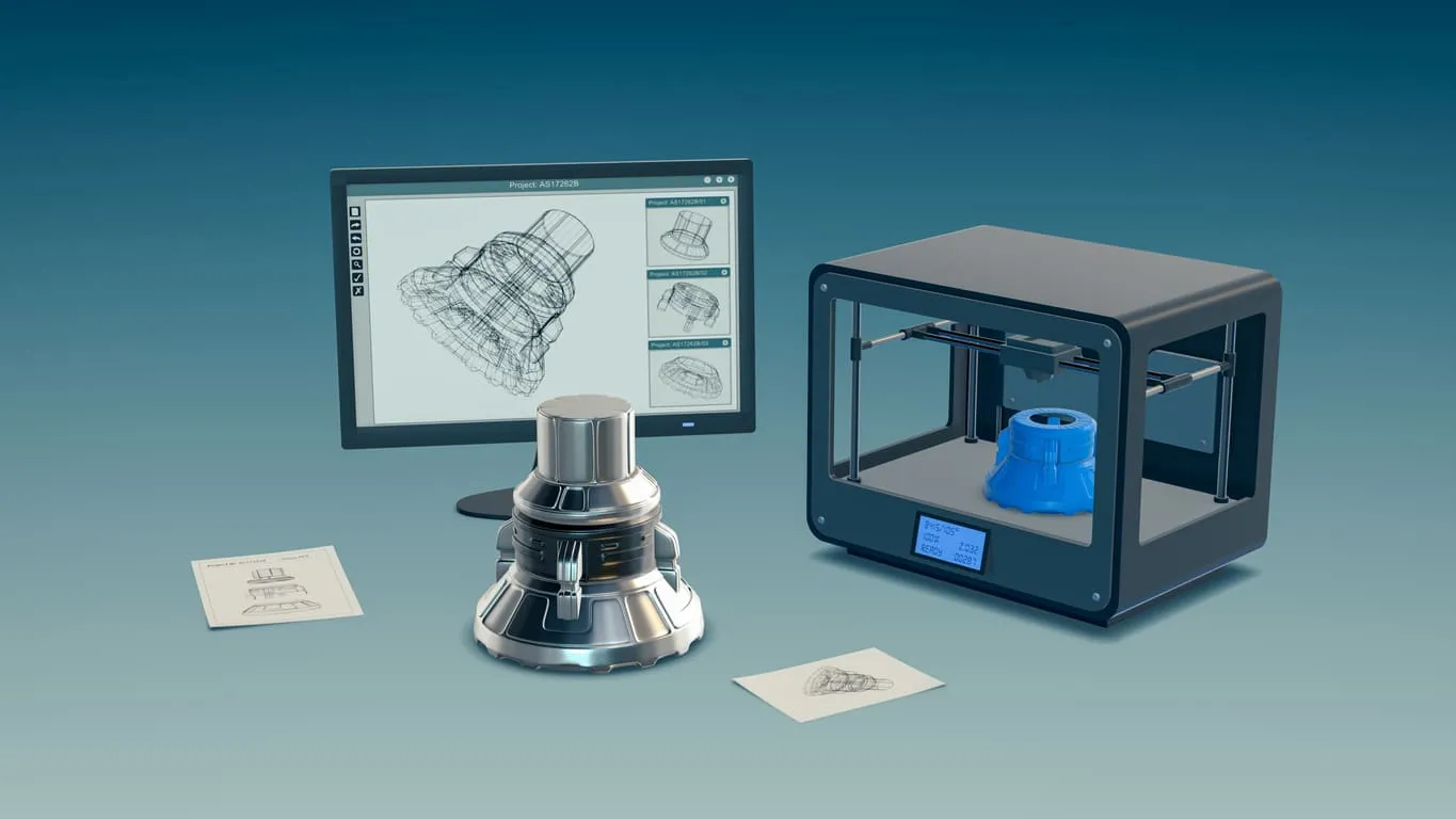
3D printers are highly versatile when it comes to the kinds of parts they can manufacture. Depending on the specific 3D printing technology being used, you can produce parts in a wide variety of geometries and sizes. However, there are still 3D printing geometry restrictions for even the most advanced 3D printing technologies in existence today.
In this article we take a closer look at the size and geometric limitations that are important to understand when creating 3D CAD models for additive manufacturing. Understanding these limitations is vital no matter if you’re manufacturing basic parts or highly complex parts with intricate design features.
The Build Sizes of 3D Printing Technologies
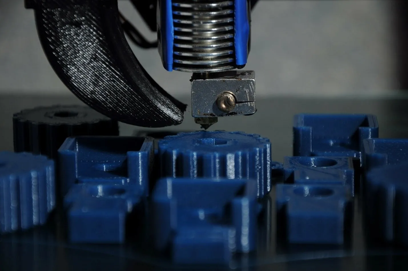
One of the most important restrictions facing every 3D printing technology is the physical size of the part that can be printed. While each printer has its own size limitations, it’s generally best to use an industrial printer for parts that are larger. Moreover, one of the best solutions for manufacturing large 3D printed parts is to split the parts into multiple components that can be printed separately and then assembled after printing concludes.
While each specific 3D printer has its own build size limitations, here are common build sizes for the following 3D printing processes:
- FDM - 200 x 200 x 200 mm (desktop) / 900 x 600 x 900 mm (industrial)
- SLA - 145 x 145 x 175 mm (desktop) / 1500 x 750 x 500 mm (industrial)
- SLS - 750 x 550 x 550 mm
- DMLS/SLM - 500 x 280 x 360 mm
- MJF - 380 x 285 x 380 mm
Minimum Wall Thickness For 3D Printing Processes
In addition to build size, another critical factor to consider in your 3D printed part designs is wall thickness. Each 3D printing technology has a minimum wall thickness that must be carefully followed to avoid part failure. For most part designs, it’s not possible to 3D print very thin walls unless they are wider than the minimum printable feature size for each 3D printing technology.
Here are the minimum wall thickness requirements for each 3D printing process:
- FDM - 0.8 mm
- SLA/DLP - 0.5 mm
- SLS - 0.7 mm
- MJF - 0.5 mm
- DMLS/SLM - 0.4 mm
Understanding the Importance of Manifold 3D Models
Another vital consideration for part designers to consider in their 3D printed models is the requirement for the part to be completely manifold—also called “watertight”. Manifold means that each edge of the part should be connected to exactly 2 polygons. Moreover, the part should not include any holes unless they’re necessary for the intended design. If your model isn’t manifold, there is a risk that the 3D printing software with misinterpret the instructions for the 3D printer. Non-manifold 3D print designs could result in the print having holes, inconsistent layers, and additional defects. These issues will most likely cause your part to not be printable.
Each 3D print consists of polygons, which are commonly called “faces”. These are the flat squares found in polygonal, non-CAD models. Each polygon represents the surface between 3 or 4 edges. Moreover, each of these edges must have 2 polygons connected on either side. The problem is that non-manifold defects are often not clear at the modeling stage. The best method for validating if a model is printable is to use specialized software programs that can highlight features of your design that could cause problems during 3D printing.
The Impact of NURBS on 3D Printing Smooth Surfaces
CAD software utilizes non-uniform rational basis splines (NURBS) to show the surfaces of a 3D model. When you export your model to the STL file format, it’s vital to ensure that there is an adequate number of polygons being utilized to represent the surfaces. Doing so helps to validate that your part will have a smooth surface finish after it’s 3D printed.
If your 3D model is exported with an insufficient number of polygons, the edges that connect individual polygons will most likely be visible in your 3D printed part. In fact, this visual appearance is more pronounced in larger models because the polygons are more visible on curved surfaces. On the other hand, if you have too many polygons in the export of your 3D model, then the file size will exceed the limit of most 3D printers. Also, it’s important to note that when you create meshes of polygons, finer the meshes will result in larger file sizes that can be problematic for the 3D printer.
Get multiple quotes for your parts in seconds