Engineering drawing explained, why is it a crucial design skill?
Engineers have used technical drawings to convey information since the days of the ancient Greeks and Romans. We take a deep dive into just why engineering drawing is still such a crucial skill and what tools professionals use to create engineering drawings.
What is an engineering drawing?
Often referred to as mechanical drawings, detail drawings, blueprints, or technical drawings, engineering drawings are a standard form of communication used by engineers, architects, electricians, construction experts, and many other professionals.
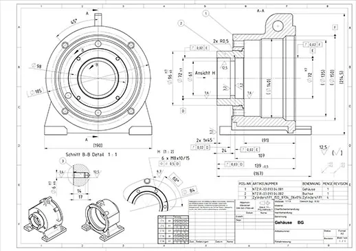
Engineering drawings are used to communicate design concepts and design intent using a standardized pictorial language comprised of lines, shapes, and symbols. They are sophisticated technical drawings that provide details on the geometry, dimensions, materials, and tolerances of an object.
The standard engineering drawing format is a 2D representation that depicts an object from a variety of views. Objects can be shown from:
- The front
- The back
- The top
- The bottom
- The sides
In some cases, not all views will need to be shown, just the ones that provide crucial details. Some engineering drawings will show additional viewpoints that show the inner workings of an object such as:
- Section views
- Crop views
- Break views
Information on the person who created the drawing is usually contained in a title box. The information contained in an engineering drawing is used to refine designs, develop prototypes, and construct and maintain objects. In many cases, one simple part will require a series of drawings to fully explain its construction.
This is where the work of a mechanical designer comes into play.
Discover Dassault Système's store solutions for engineering drawing
Creating complex 2D and 3D engineering drawings requires sophisticated software that can be adapted to suit a range of purposes. Dassault Systèmes specializes in computer aided engineering drawing solutions.

xDraftSight
Browser-based 2D CAD, built on the 3DEXPERIENCE platform
What are the different types of engineering drawing?
There are four main categories of engineering drawing used by professionals: civil engineering drawing, mechanical engineering drawing, geometric drawing, and electronics and electrical drawing.
Browse all the Dassault Systèmes store applications
We feature in our store some of our best software to design, collaborate and innovate throughout the entire product lifecycle.
Content related to engineering drawing
Plan drafting
Bring your vision to life with powerful architectural plan drafting software
Architectural drawing
How architectural drawing software is helping us to build a better future
2D CAD drafting
Creating precision architectural drawings with CAD drafting software
CAD
Why CAD, Computer Aided Design, is such a powerful tool
2D to 3D
Converting a 2D drawing to a 3D model – how it is done and why
Architects vs Draftsmen
What is the difference between an architect and a draftsman?
What are the components of an engineering part drawing?
A basic engineering drawing is made up of a series of components. While these elements can vary in number and complexity according to the design, we can take a general look at some common engineering drawing basics.
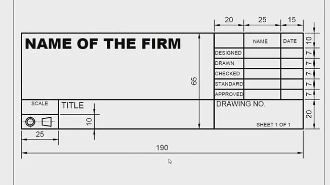
Title blocks
Also known as information blocks, title blocks usually appear in the bottom right corner of an engineering drawing. They contain information on the author of the drawing, the person who approved the drawing, the materials used, the coatings required, the names of the parts, and other important details.
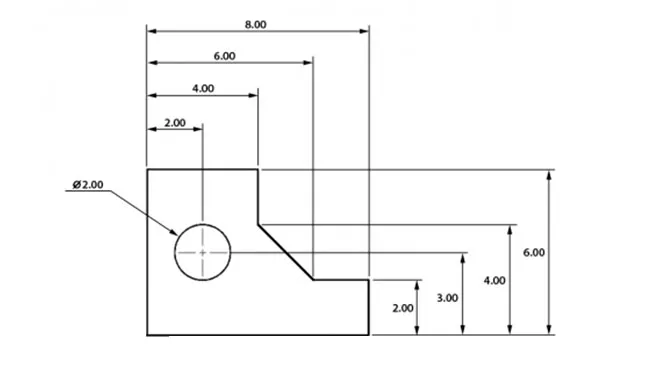
Dimensions and measurements
Dimensions and measurements are included to show the position, size, orientation, and geometric properties of parts. Dimensions and measurements are usually drawn using numerals that correspond to the appropriate units of measurement and are depicted as dimension lines along the object. Dimensions can be placed as unidirectional dimensions that are to be read from the bottom of the drawing or as aligned dimensions that are read from the bottom and right side of the drawing.
Engineering drawing: categorizing lines in blueprints
An engineering drawing employs various types of lines, including dimension lines, to illustrate both hidden and visible parts of an object.
Hidden line
Hidden lines, as the name suggests, show the parts of an object that cannot be seen from the depicted viewpoint. They are usually drawn as evenly broken lines.
Continuous line
Continuous lines are the main line used in engineering drawings. They depict the physical boundaries of an object. The outer contours of the object will have thicker continuous lines, while the inner contours are depicted with thinner continuous lines.
Cutting plane line
A cutting plane line shows the path of a cutout in cutout view. It is used to show what holes will be visible in an object.
Center line
Center lines depict the holes and symmetrical features in a drawing. Center lines make it easier for the reader to understand the drawing.
Dimension and extension line
Dimension lines have two arrowheads on each side with a measurement in the middle. They provide information on the geometric proportions of the object.
Broken view line
Broken view lines are used to provide information concisely. Made up of dots or dashes or both, these lines indicate that a section of the drawing cannot be shown due to space restrictions but has the same geometric proportions as noted in the drawing.
What are the common tools and software used in engineering drawing?
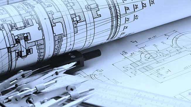
Drawing Instruments
Engineering drawing instruments are used to produce manual drawings. They ensure that the lines drawn are accurate and conform to the desired shape. Common engineering drawing instruments include T-squares, compasses, protractors, set squares, and French curves.
CAD Software
Engineers and designers leverage computer-aided engineering drawing and drafting tools, including CAD files, to generate highly intricate technical drawings. 3D modeling tools are frequently employed to transform 2D engineering drawings into three-dimensional models, enhancing the visualization and comprehension of the design.
Are there standards and conventions in engineering drawing?
To ensure that engineering drawings can be easily interpreted and are accurate they must conform to a common engineering drawing scale. All types of engineering drawings must adhere to standards and conventions. The exact standards and conventions used depend on where the drawing has been produced and for what purpose.
An engineering drawing designed for use in the United States must conform to the rules set by the American National Standards Institute (ANSI). In the United Kingdom, the British Standards Institution (BSI) sets the conventions for engineering drawings. The International Organization for Standardization (ISO) provides conventions and standards for use in engineering drawings for international audiences.
Engineering drawing - Conclusion & Perspectives
Engineering drawings are highly technical documents that provide detailed information on objects, structures, machinery, and products. Designers and engineers use these documents to refine designs, to develop 3D digital models, and to construct physical objects.
Architects, mechanical engineers, mechanical designers, construction excerpts, civil engineers, and electricians all use engineering documents. A concise engineering document is crucial to producing a product, machine, or structure that is efficient and works according to its design intent. Anyone interested in a career in architecture design, construction, or engineering must have a good knowledge of how to create and interpret engineering drawings.
Why choose Dassault Systèmes for your engineering drawing needs?
Break away from IT restraints with the 3DEXPERIENCE Platform
Creating an accurate and concise engineering drawing is both a skill and an art. As well as being able to manually create an engineering drawing, professionals require sophisticated computer aided engineering drawing software for complex assembly drawing.
The 3DEXPERIENCE platform harnesses the latest cloud computing technology to provide unparalleled design freedom.
With the 3DEXPERIENCE platform, professionals can access a range of powerful CAD and PLM tools using any internet-enabled device. Users can share, store, and work on projects with colleagues from any location, at any time.


Partner with a CAD company with more than 40 years of experience
For more than four decades Dassault Systèmes has been renowned for developing powerful, intuitive, and effective CAM, CAD, and PLM software. Our roles enable designers and engineers across a broad range of industry sectors to create, innovate, and collaborate like never before.
Dassault Systèmes is made up of 11 brands dedicated to providing customized solutions for professional engineers and designers. Discover the entire range of Dassault Systèmes roles today.
Explore inspiring content
Frequently asked Questions
The importance of engineering drawing in product development
Conveying highly complex engineering information and requirements can be a difficult task using just words. A written document describing a proposed product could run to thousands of pages of detail. An engineering drawing, however, can provide all the essential details quickly and concisely. In terms of product development, pictures are worth more than words!
Engineering drawings are an integral part of the process of designing a product. The initial set of engineering drawings will depict all the parts required to produce the product and show how they fit together. Without this, engineers cannot accurately determine the shape and size of the product and develop an efficient manufacturing plan for it.
As designers and engineers work together to refine the product, many sets of engineering drawings may be produced during the product development and prototyping stages. In many cases, a designer will create a digital 3D model based on the information contained in the engineering drawings that can then be used for prototyping and simulations.