Antenna Magus Array Synthesis
Antenna Array Design Made Easy
The Antenna Magus Array Synthesis Tool
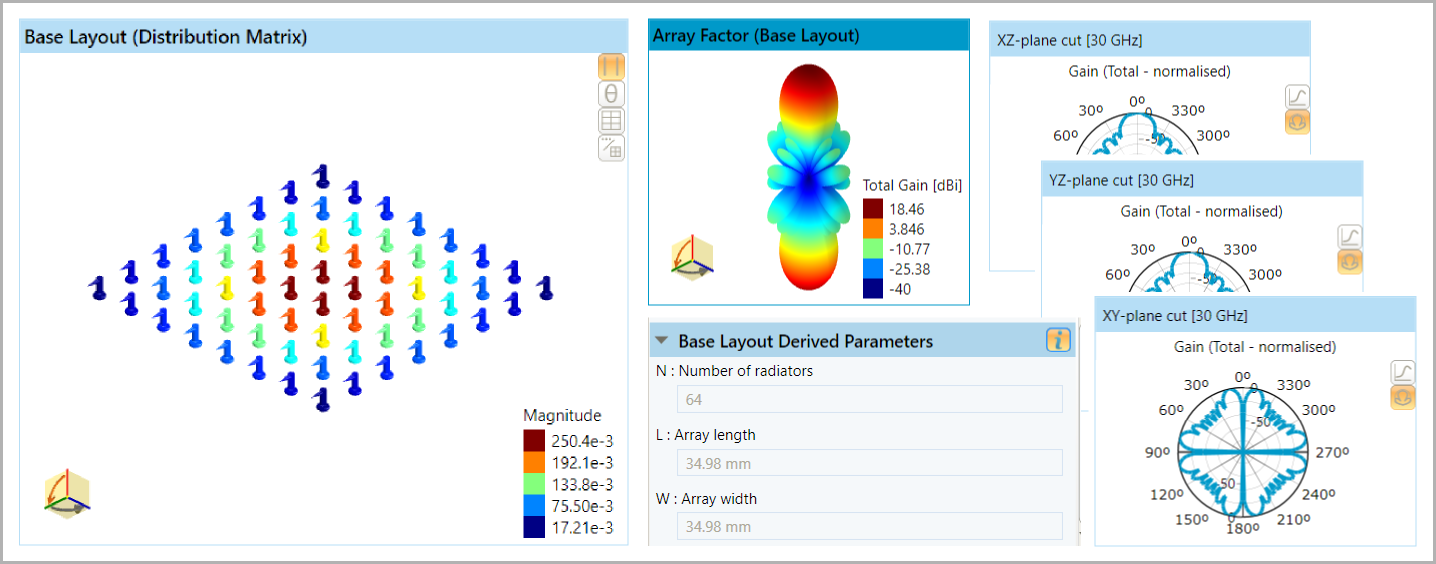
The array synthesis tool helps with the initial stages of array design. It assists engineers in synthesizing arrays of various shapes, such as linear, planar and circular with different excitation distributions and radiating elements. The array synthesis tool contains several design algorithms that determine the required array parameters for given objectives. Users can also import array layouts into Antenna Magus and modify the layouts using operators.
A useful application for the array synthesis tool is the distribution matrix (DM) import functionality. It allows users to specify customized array layouts using tab-separated value (tsv) files. Antenna Magus reads each element's spacing (x,y,z), amplitude and phase and calculates the synthesized array using the specified element pattern.
Antenna Array Types
The Antenna Magus information browser provides more information about how to use the array synthesis in: Antenna Array Synthesis in Antenna Magus and in Help: How do I use the Array Synthesis tool? The latter article also describes the different excitation tapers in more detail, and provides references for further research.
- Linear
- Planar
- Circular
- Concentric Circular
- Cylindrical
- Triangular
Broadside with Default Taper
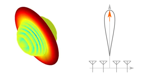
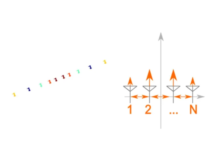
This synthesis algorithm designs a linear array for a specified directivity or beamwidth. Antenna Magus arranges the elements of the array along the x-axis, with the resulting pattern being symmetrical around the x-axis and the peak directivity in the y-z plane (broadside).
This design algorithm sets the inter-element spacing always at 0.49 λ. The specification of a directivity of less than 20 dB, or a beamwidth of greater than 20°, results in all the side-lobes to be equal or -20 dB below the main beam directivity [Dolph-Chebychev excitation taper]. For higher gain designs, the first five side lobes are -20 dB below the main beam directivity [Villeneuve excitation taper].
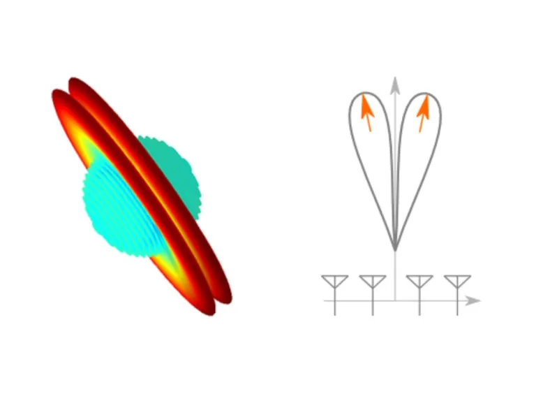
Broadside Directivity and Scan Angle
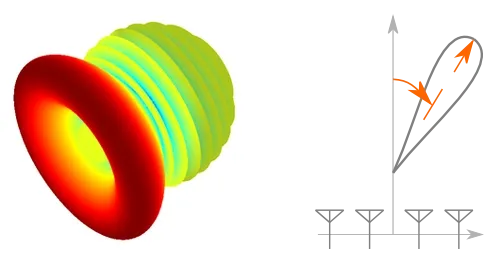
This synthesis algorithm designs a linear array for a specified directivity or beamwidth and a scan angle. Antenna Magus arranges the elements of the array along the x-axis. The resulting pattern being rotationally symmetric around the x-axis and the peak directivity being at the specified scan angle away from the y-z plane.
This design algorithm sets the inter-element spacing always at 0.49 λ. The specification of a directivity of less than 20 dB, or a beamwidth of greater than 20°, results in all the side-lobes to be equal or -20 dB below the main beam directivity [Dolph-Chebychev excitation taper]. For higher gain designs, the first five side lobes are -20 dB below the main beam directivity [Villeneuve excitation taper]. The specification of the scan angle introduces an inter-element phase offset in the excitation.
Broadside Directivity and Excitation Taper
This synthesis algorithm designs a linear array for a specified directivity or beamwidth and a scan angle. Antenna Magus arranges the elements of the array along the x-axis. The resulting pattern is rotationally symmetric around the x-axis and the peak directivity is at the specified scan angle away from the y-z plane.
This design algorithm sets the inter-element spacing always at 0.5 λ. Antenna Magus enables the selection of the excitation taper between equal excitation [Uniform], uniform side lobe level [Dolph-Chebychev] and first few side lobes uniform [Villeneuve]. Then they can specify side lobe level and number of side lobes, where applicable.
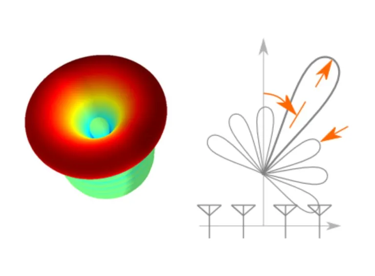
Broadside Directivity, Scan Angle and Taper
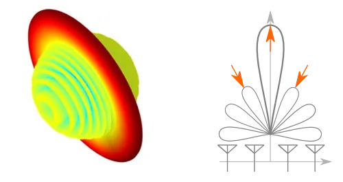
This synthesis algorithm designs a linear array for a specified directivity or beamwidth, scan angle and excitation taper. The user can specify the excitation taper to control the sidelobes while using the scan angle (specified from broadside) to design an array that squints at a specific angle. Antenna Magus can design this array can with the elements arranged along any of the three major axes. The resulting pattern is rotationally symmetric around the chosen axis and the peak directivity is at the specified scan angle away from the plane normal to this axis.
This design algorithm can use the inter-element spacing as an input. Values between 0 λ and 5 λ are possible. A spacing of over 0.5 λ can lead to unwanted grating lobes appearing together with the required main lobe. Hence, the peak directivity could be lower than designed for. The energy in the grating lobe can be compensated for in the design requirements of the main lobe. The direction of the main lobe can be specified between -90° and 90 degrees. Users can select the excitation taper to be equal excitation [Uniform], uniform side lobe level [Dolph-Chebychev] and first few side lobes uniform [Villeneuve]. Then they can specify side lobe level and number of side lobes, where applicable.
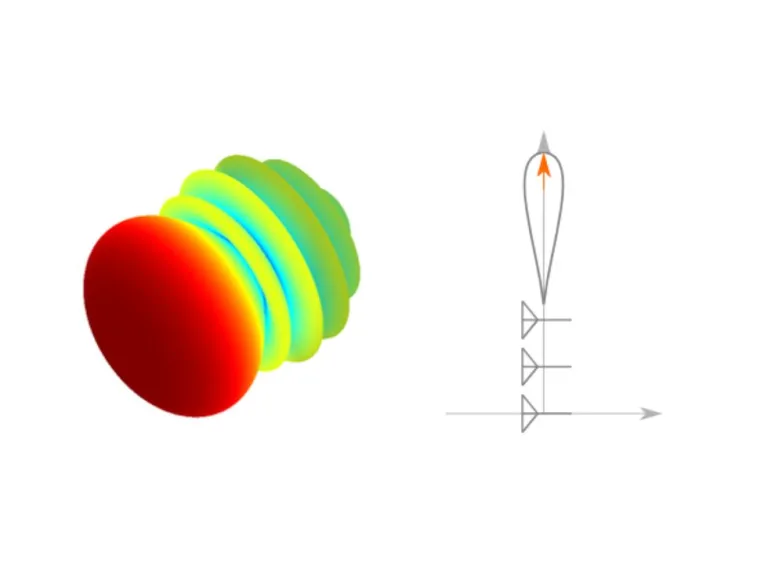
End-Fire Directivity or Beamwidth
This synthesis algorithm designs a linear array for a specified directivity or beamwidth. Antenna Magus arranges the elements of the array along the x-axis. The main lobe of the resulting pattern is a body of rotation about the x-axis, with the peak directivity in the +x direction.
The inter-element spacing is always 0.49 λ when this design algorithm is used. If a directivity of less than 20 dB, or a beamwidth of greater than 20°, is specified, all the side-lobes are equal and -20 dB below the main beam directivity [Dolph-Chebychev excitation taper]. For higher gain designs, the first five side lobes are -20 dB below the main beam directivity [Villeneuve excitation taper]. The specification of the scan angle introduces an inter-element phase offset in the excitation.
End-fire Directivity and Excitation Taper
This synthesis algorithm designs a linear array for a specified directivity or beamwidth and excitation taper. The direction of peak directivity can be set to any of the Cartesian axis directions. The specification of the excitation taper controls the sidelobes. The resulting pattern of this array is always rotationally symmetric around the chosen axis.
This design algorithm can use the inter-element spacing as an input. Values between 0 λ and 5 λ are possible. If a spacing of over 0.5 λ is used, unwanted grating lobes are present together with the required main lobe. Therefore, the peak directivity could be lower than designed for. The energy in the grating lobe can be compensated for in the design requirements of the main lobe. Users can select the excitation taper to be equal excitation [Uniform], uniform side lobe level [Dolph-Chebychev] and first few side lobes uniform [Villeneuve]. Then they can specify side lobe level and number of side lobes, where applicable
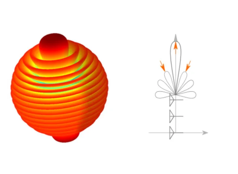
Broadside Null with Directivity and Taper
This synthesis algorithm designs a linear array that has a broadside null, with a specified directivity either side of the null and excitation taper. The specification of the excitation taper allows the sidelobes to be controlled. Antenna Magus can design this array with the elements arranged along any of the three major axes. The resulting pattern is rotationally symmetric around the chosen axis and the null is in the plane normal to that axis.
The inter-element spacing designed by this algorithm is always 0.5 λ. Users can select the excitation taper to be equal excitation [Uniform] and near-in side-lobes at quasi-uniform specified level [Bayliss]. The side lobe level and number of side lobes can be set when using the Bayliss taper.
Specify the Layout Directly
This algorithm allows the specification of the array and its excitation directly. Antenna Magus does not adjust the array layout at all to achieve specific electrical objectives. Therefore, users can evaluate a custom array layout, using the array routines in Antenna Magus.
The array orientation, the inter-element spacing, the spacing method and the excitation taper can all be specified. Users can select the excitation taper to be equal excitation [Uniform], uniform side lobe level [Dolph-Chebychev] and first few side lobes uniform [Villeneuve]. Then they can specify side lobe level and number of side lobes, where applicable.
Broadside Directivity or Beamwidth
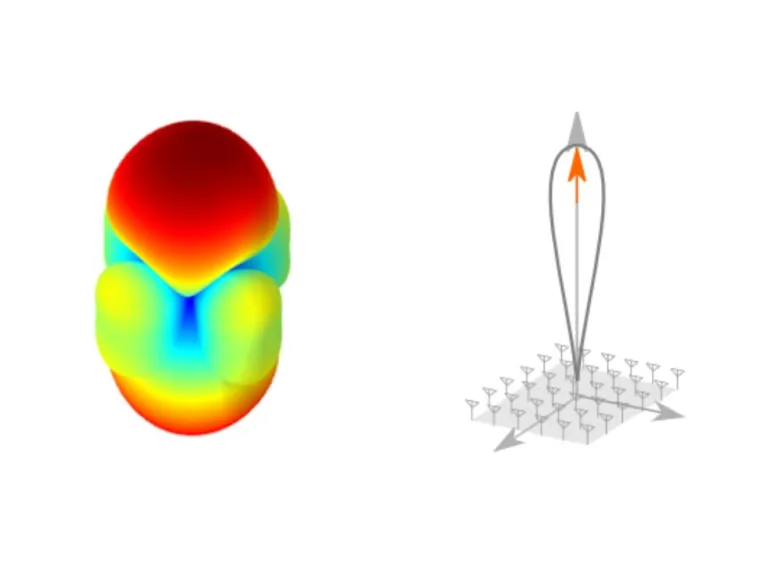
This synthesis algorithm designs a planar array for a specified directivity or beamwidth. Antenna Magus always arranges the array elements in the x-y plane, centered on the z-axis, resulting in a bi-directional beam along the positive and negative z-axis.
When this design algorithm is used, the inter-element spacing is always 0.45 λ, with an equal number of radiators in the x- and y-direction when gain is specified, and a different number of radiators in the x- and y-direction when different 3-dB beamwidths are specified in the x- and y-plane. The excitation per element is the product of two linear array excitations, one excitation is laid out along the x-axis and the other is laid out along the y-axis. If a directivity of less than 20 dB, or a beamwidth of greater than 20°, is specified, the side-lobes per linear excitation are designed for -20 dB below the main beam directivity [Dolph-Chebychev excitation taper]. For higher gain designs, each linear excitation is designed to have the first five side lobes -20 dB below the main beam directivity [Villeneuve excitation taper]
Broadside Directivity and Excitation
This synthesis algorithm designs a planar array for a specified directivity or beamwidth and excitation taper. The excitation taper controls the side-lobe level and distribution. Antenna Magus always arranges the array elements in the x-y plane, centered on the z-axis, resulting in a bi-directional beam along the positive and negative z-axis.
When this design algorithm is used, the inter-element spacing is always 0.5 λ, with an equal number of radiators in the x- and y-direction when gain is specified, and an unequal number of radiators in the x- and y-direction when different 3-dB beamwidths are specified in the x- and y-planes. The excitation per element is the product of two linear array excitations, one laid out along the x-axis and the other laid out along the y-axis.
Users can set the excitation taper to equal excitation [Uniform], all side-lobes equal [Dolph-Chebyshev] or first few side-lobes equal [Villeneuve]. The side-lobe level and number of side lobes (where applicable) can then be set.
Broadside Null with Specific Directivity
This synthesis algorithm designs a planar null array for a specified directivity and excitation taper. The excitation taper controls the side-lobe level and distribution. Antenna Magus always arranges the array elements in the x-y plane, centered on the z-axis, resulting in a bi-directional beam along the positive and negative z-axis.
This design algorithm always sets the inter-element spacing to 0.5 λ, with an equal number of radiators in the x- and y-direction. The relative placement of the element on a Bayliss curve between the center (origin) and the maximum outer radius of the array determines the excitation.
Users can set the excitation taper to equal excitation [Uniform], or near-in side-lobes at quasi-uniform specified level [Bayliss]. The side-lobe level and number of side lobes (where applicable) can then be set. However, the nature of the design makes this specification difficult to control, leading potentially to results not as specified.
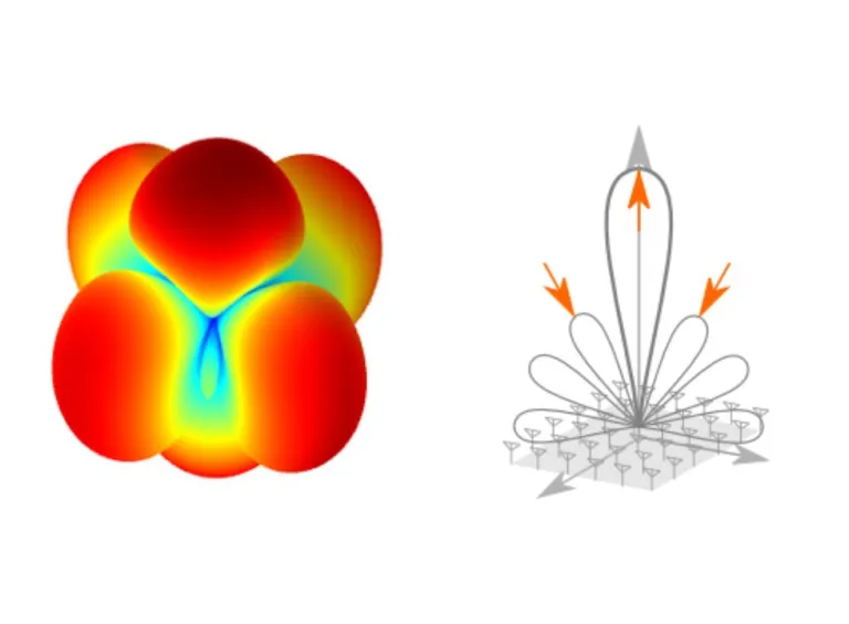
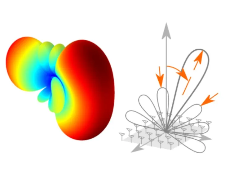
Broadside Directivity, Scan Angle and Taper
This synthesis algorithm designs a planar array for a specified directivity or beamwidth, scan angle and excitation taper. The excitation taper controls the side-lobe level and distribution while the scan angle (specified from broadside) is used to design an array that squints at a specific angle. Antenna Magus always arranges the array elements in the x-y plane, centered on the z-axis, resulting in a bi-directional beam along the positive and negative z-axis.
This design algorithm can use the inter-element spacing as an input. Values between 0λ and 5λ are possible. An equal number of radiators in the x- and y-direction is chosen when gain is specified, and an unequal number of radiators in the x- and y-direction is chosen when different 3-dB beamwidths are specified in the x- and y-planes. The excitation per element is the product of two linear array excitations, one laid out along the x-axis and the other laid out along the y-axis.
Users can set the excitation taper to equal excitation [Uniform], all side-lobes equal [Dolph-Chebyshev or first few side-lobes equal [Villeneuve]. The side-lobe level and number of side lobes (where applicable) can then be set.
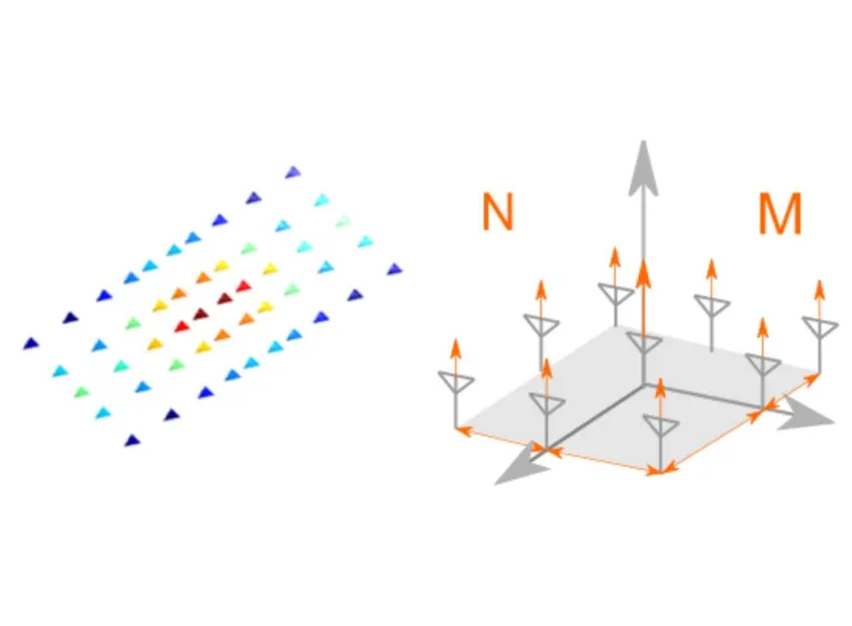
Specify the Layout Directly
This algorithm allows the specification of the array and its excitation directly. Antenna Magus does not adjust the array layout at all to achieve specific electrical objectives. Therefore, users can evaluate a custom array layout, using the array routines in Antenna Magus. The elements of the array are arranged in the x-y plane, centered on the z-axis.
The user can specify the number of elements, the inter-element spacing and the spacing method in the x- and y-direction, respectively. Users can select the excitation taper to be equal excitation [Uniform], uniform side lobe level [Dolph-Chebychev] and first few side lobes uniform [Villeneuve]. Then they can specify side lobe level and number of side lobes, where applicable. The excitation per element is the product of two linear array excitations, one laid out along the x-axis and the other laid out along the y-axis. The side-lobe specification is not guaranteed, since the layout is not adjusted to achieve these goals.
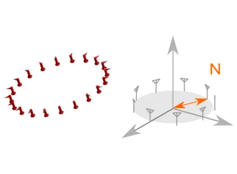
Azimuthal Direction of Peak Directivity
This synthesis algorithm designs a circular array for a specified directivity in a given azimuthal direction. Antenna Magus always arranges the array elements in the x-y plane, centered on the z-axis.
Users can specify azimuthal direction, together with either directivity, a given radius or a specific number of elements. When they specify an azimuthal direction and directivity, the design algorithm designs the array for the least number of elements with adjacent element spacing of approximately a quarter wavelength.
When specifying the number of elements, the smallest possible radius is designed for, while when specifying the array radius, the smallest number of elements are chosen; both with adjacent element spacing of approximately a quarter wavelength.
Specify the Layout Directly
This algorithm allows the specification of the array and its excitation directly. Antenna Magus does not adjust the array layout at all to achieve specific electrical objectives. Therefore, users can evaluate a custom array layout, using the array routines in Antenna Magus. The elements of the array are arranged in the x-y plane, centered on the z-axis.
The number of elements in the array, and the radius of the array can be specified.
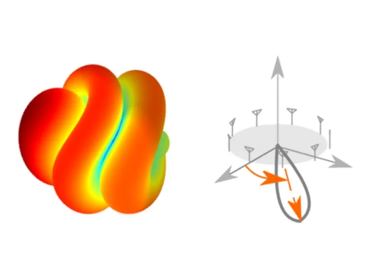
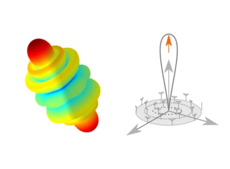
Gain or Beamwidth
This synthesis algorithm designs a circular array (made up of multiple concentric rings of elements) for a specified directivity or beamwidth. Antenna Magus always arranges the array elements in the x-y plane (cantered around the z-axis) and main-beam radiation along the positive and negative z-axis directions. When isotropic array elements are assumed, the radiation pattern of this array is a figure-of-rotation around the z-axis.
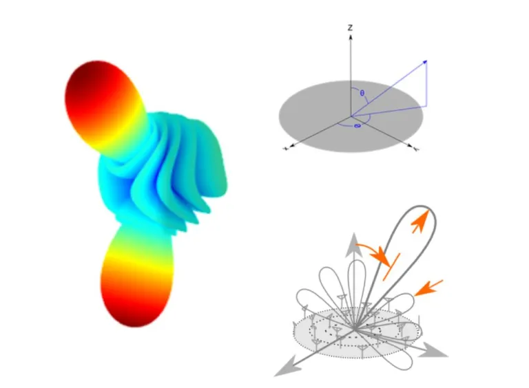
Scan Angle and Gain
This synthesis algorithm designs a circular array (made up of multiple concentric rings of elements) for a specified directivity or beamwidth. Antenna Magus always arranges the array elements in the x-y plane (cantered around the z-axis) and main-beam radiation along the positive and negative z-axis directions. When isotropicThis synthesis algorithm designs a concentric circular array (consisting of a set of concentric rings of array elements) for a specified directivity in a given azimuthal and elevation direction. Antenna Magus always arranges the array elements in the x-y plane, centered on the z-axis. When isotropic array elements are assumed, the synthesized radiation pattern of this array is a mirror-image around the x-y plane.
Users can specify an azimuthal and elevation direction for the main beam together with the required directivity of the main beam. The graphic shows the definition of the angles.
Choose the excitation distribution taper as uniform (all elements excited uniformly) or based on a Taylor distribution. When using a Taylor distribution, you can choose to keep the level of the side-lobes and the number of sidelobes at this level, while the Uniform taper provides no sidelobe level control.
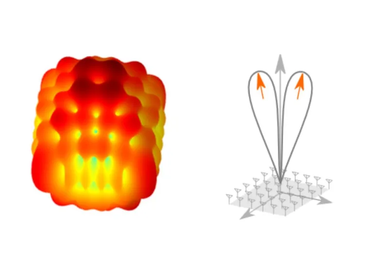
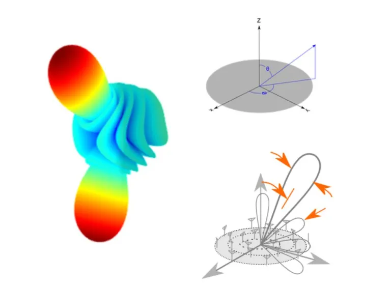
Scan Angle and Beamwidth
This synthesis algorithm designs a concentric circular array, made up of multiple concentric rings of elements. It provides a main beam with a specified beamwidth in a given azimuthal and elevation direction. Antenna Magus arrange the elements of this array in the x-y plane, centered on the z-axis. Assuming isotropic array elements, the synthesized radiation pattern of this array is a mirror-image around the x-y plane.
Users can specify an azimuthal and elevation direction for the main beam together with the required beam width of the main beam. The graphic shows the definition of the angles. When the array radiation pattern is synthesized with isotropic element patterns, the radiation pattern are always mirrored around the xy-plane.
Choose the excitation distribution taper as uniform (all elements excited uniformly) or based on a Taylor distribution. When using a Taylor distribution, you can choose to keep the level of the side-lobes and the number of sidelobes at this level, while the Uniform taper provides no sidelobe level control.
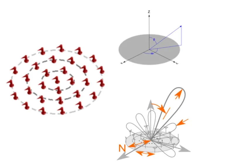
Specify the Layout Directly
This algorithm allows the specification of a concentric circular array directly. Antenna Magus does not adjust the array layout at all to achieve specific electrical objectives. This option is useful when evaluating the performance of a custom or pre-designed array layout. Antenna Magus arranges the elements of this array in the x-y plane, centered on the z-axis. The inclusion of the central element is optional.
Users can specify number of concentric rings, spacing between the rings of elements, and the minimum azimuthal spacing between elements. The azimuthal spacing is a minimum and the algorithm adjusts the spacing for each ring such that the elements in each ring are equally spaced, but are not closer than this value.
In addition to the physical array layout properties, the excitation taper of the array can be specified to allow for beam steering and side-lobe-level control. The effectiveness of element phasing and usage of a distribution taper depends on the physical layout and spacing of the array element, potentially prohibiting achieving the specified performance. The graphic shows the definition of the angles.
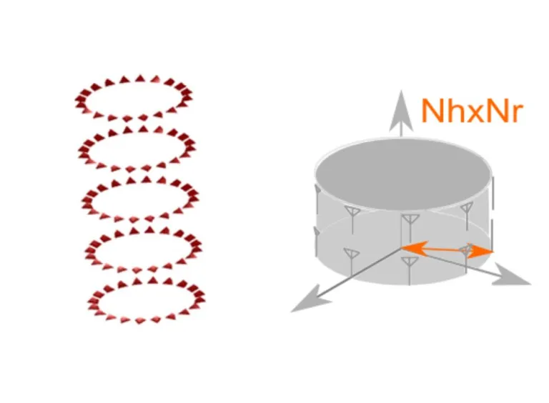
Specify the Layout Directly
This algorithm allows the specification of the array and its phase excitation directly. Antenna Magus does not adjust the array layout at all to achieve specific electrical objectives. Therefore, users can evaluate a custom array layout, using the array routines in Antenna Magus. The radius of the array lies in the x-y plane, while the height extends in the z-direction.
Physically, the number of elements along the circumference (arc), the number of elements along the height, the radius, the angular range and the element spacing along the height of the array can be set. Electrically, the incremental phase shift in radial and height direction can be set.
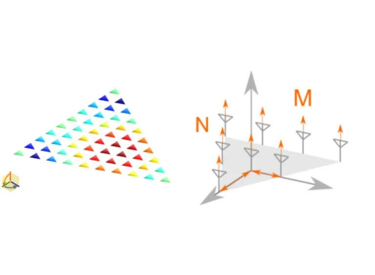
Specify the Layout Directly
This algorithm allows the specification of the array and its excitation directly. Antenna Magus does not adjust the array layout at all to achieve specific electrical objectives. Therefore, users can evaluate a custom array layout, using the array routines in Antenna Magus. The elements of the array are arranged in the x-y plane, centered on the z-axis.
Users can specify the number of elements, the inter-element spacing and the spacing method in the x- and y-direction, respectively. They can select the excitation taper to be equal excitation [Uniform], uniform side lobe level [Dolph-Chebychev] and first few side lobes uniform [Villeneuve]. Then they can specify side lobe level and number of side lobes, where applicable. The excitation per element is the product of two linear array excitations, one laid out along the x-axis and the other laid out along the y-axis for a rectangular array. From this excitation distribution, a subset for the triangular array is extracted. The side-lobe specification is not guaranteed, since the layout is not adjusted to achieve these goals.
Also Discover

Antenna Design Software
Antenna Magus Toolbox for Simplified Antenna Design

Simplify Finding Commercial/Standard Substrates, Waveguides, Connectors and Specifications
Learn What SIMULIA Can Do for You
Speak with a SIMULIA expert to learn how our solutions enable seamless collaboration and sustainable innovation at organizations of every size.
Get Started
Courses and classes are available for students, academia, professionals and companies. Find the right SIMULIA training for you.
Get Help
Find information on software & hardware certification, software downloads, user documentation, support contact and services offering