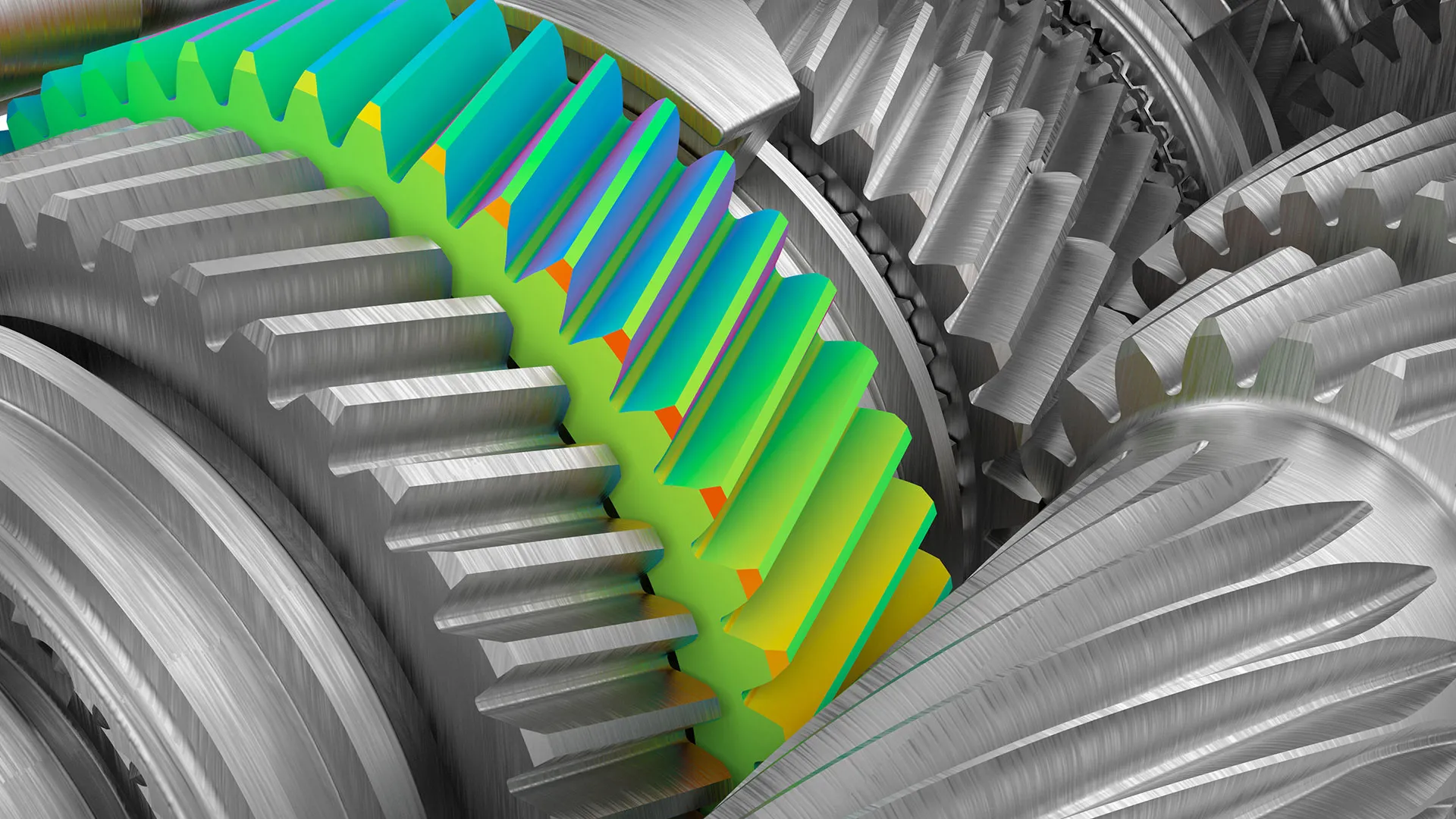
Our guide to Finite Element Analysis
When designing products and machinery, design engineers use sophisticated calculations, models, and simulations to gauge how objects physically react to various conditions. In this article, we take a closer look at the processes of finite element analysis and the finite element method.
What is finite element analysis?
When a mechanical engineer is designing a new product, a machine assembly, or a part, they need to know how it will react to various types of physical conditions. How an object performs when subjected to heat, vibration, stress, motion, or electric charges can greatly impact how it functions.
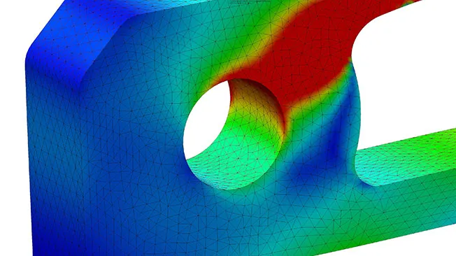
Finite element analysis, also known by the acronym FEA, is a computerized method of determining how an object will react to physical forces. The purpose of FEA is to identify different flaws within a design before an object goes into production.
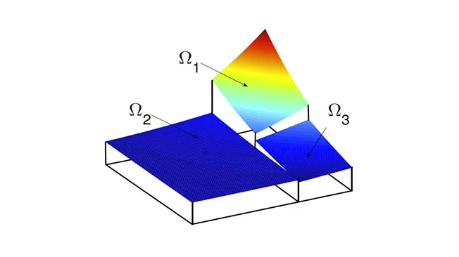
The concept of FEA centers around the idea that any object can be broken down into several smaller parts. These parts are then individually analyzed to determine how they will cope with real-world conditions. This process has been greatly facilitated by the development of technology that can convert 2D drawings into 3D models.
FEA was first developed in the 1970s in conjunction with the very first computer aided design software. By using FEA on digital 3D models, designers and engineers can reduce the need to create physical prototypes. This has led to a shift in the roles of architects and draftsmen, with more emphasis now placed on digital design
Discover professional mechanical design solutions at the Dassault Systèmes store
Mechanical engineers and designers rely on the powerful CAD software from Dassault Systèmes to create highly detailed, complex 3D models.

SOLIDWORKS Design
From mechanical 2D or 3D design to manufacturing, accelerate your processes at an affordable price.

PLM Express Design Engineering
Empower smart product design and boost engineering precision
SOLIDWORKS xDesign
Get ready for the next generation of design solution, developed by the same team that brought you SOLIDWORKS 3D CAD
How does finite element analysis work?
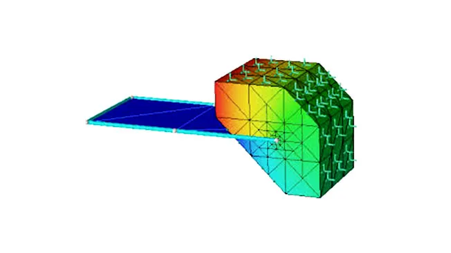
FEA is a crucial component of most CAD simulation software. It works by using the finite element method (FEM) which is a mathematical technique that breaks an object into numerous pieces and then reconnects the pieces at certain points. The pieces are known as elements, and the connection points are referred to as nodes.
FEM uses complicated algebraic equations to provide data that engineers can analyze as part of the FEA process. While FEA is a relatively new technique, the roots of FEM go back to the 1950s.
The FEA process begins with an engineer or designer creating a lifelike 3D model using sophisticated CAD software. This model is then put through a series of FEM calculations to break it into smaller elements. Engineers then put these elements through a series of tests and simulations to determine how the elements react to certain situations.
What are the physical effects that can be reproduced through FEA?
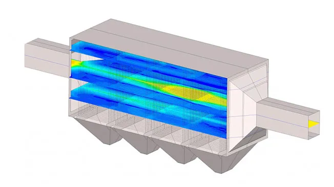
Mechanical vibration
Mechanical vibration analysis studies how a part, component, or an entire machine assembly or structure reacts to movement and vibration during its normal operation. Mechanical vibration analysis is often used to test how buildings and engines will react to real-world conditions.
Electrostatics
Electrostatic analysis is an electromagnetic simulation that measures how electric charges are distributed throughout an object when there is no magnetic field present. It is commonly used when designing and testing electrical products and computers.
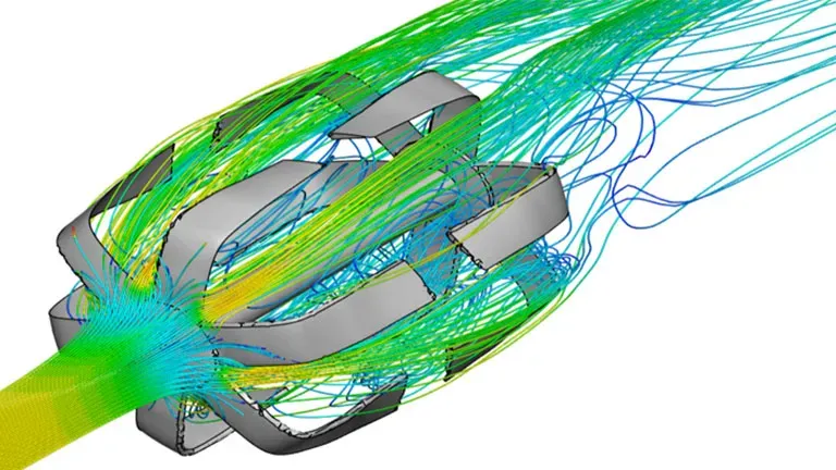
Fluid flow
Engineers use FEA techniques to analyze how fluid, gas or other liquids flow through and across an object. This technique is often employed in the automotive and aerospace industries to test aerodynamics. It is often referred to as computational fluid dynamics or CFD.
Fatigue
A fatigue FEA analysis is conducted to determine when a structure or machine will fail after repeated loads are put on and taken off it. After a certain number of cycles, cracks will show in the structure, providing crucial data on the breaking point of the object.
Motion
Motion analysis is used to determine how an object reacts to varying degrees of velocity and acceleration. It is also used to determine the reactions between moving components. Mechanical engineers use motion analyses to find the optimum way of assembling parts.
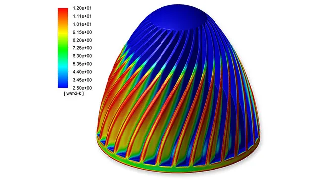
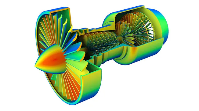
Heat transfer
Heat transfer analysis determines how temperature is distributed throughout a system. The temperature can be static, or it may fluctuate, depending on the nature of the object. Heat transfer analysis shows at which point a system may become overheated and fail.
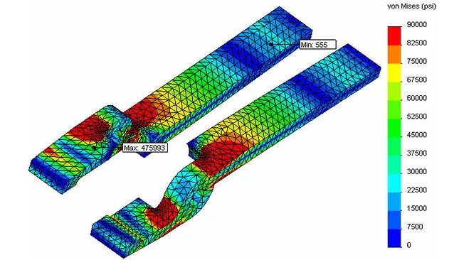
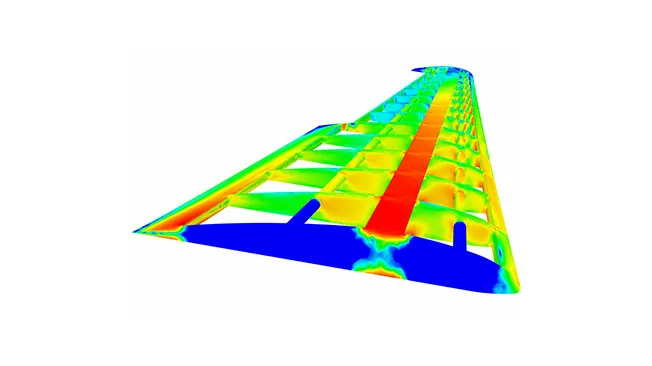
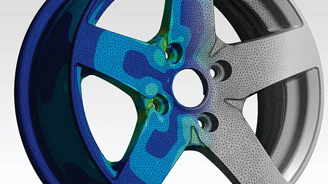
Mechanical stress
Mechanical stress is similar to both motion analysis and fatigue analysis. It is another method used to determine how an object will react to external loads. It is used to determine how an object will deform or break under stress. This technique is commonly used to develop industrial structures, sub-sea components, aircraft, and military equipment.
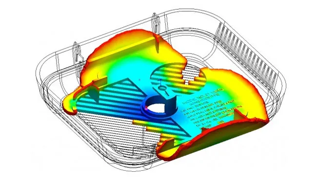
Mold flow analysis
Plastic injection molding analysis provides data on how resin will fill a mold used to cast products. Understanding how resin will fill the mold allows engineers to optimize their designs for reduced waste and increased strength. Many common products are produced using plastic injection moldings, such as bottles, casings, and automotive components.
Browse all the Dassault Systèmes store applications
We feature in our store some of our best software to design, collaborate and innovate throughout the entire product lifecycle.
Contented related to FEA
What are the different types of FEA?
- XFEM
- GFEM
- hp-FEM
- DG-FEM
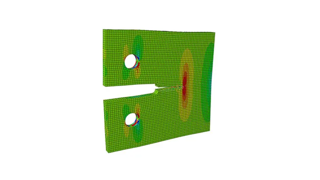
Extended Finite Element Method (XFEM)
The extended finite element method (XFEM) was invented in 1999 by mechanical engineer Ted Belytschko. It is a complex technique used to simulate how cracks form in structures and components.
Generalized Finite Element Method (GFEM)
The generalized finite element method (GFEM) is a similar technique to XFEM. It is used to solve issues with designs that have highly complex boundaries or micro-scales.
hp-Finite Element Method (hp-FEM)
The hp-finite element method (hp-FEM) is a refinement of the basic FEM process. It is used to change the size and the polynomial degree of FEA elements.
Discontinuous Galerkin Finite Element Method (DG-FEM)
The discontinuous Galerkin finite element method (DG-FEM) is used to solve highly complex problems posed by objects with complicated and elaborate geometry. Using this method, the equation for one FEA element does not relate to the equation of any other FEA element.
What are the benefits of FEA?
FEA has many benefits when it comes to product development. The FEA process can greatly improve product performance and reliability. Since it is a computerized system that uses digital models, it decreases the need for physical prototyping and testing.
FEA makes it easier for engineers to evaluate and compare different designs and material choices. Engineers and designers can optimize their designs and reduce waste and material usage. This results in reduced costs across the entire product development cycle.
Explore Dassault Systèmes solutions
Discover the powerful browser-based modeling solutions from Dassault Systèmes. You can design whatever you wish, wherever you are with 3DEXPERIENCE.
Connecting data & people to foster innovation
The 3DEXPERIENCE platform on the cloud gives you access to a various set of applications that allow you to design, simulate, inform and collaborate on a project.
What are the disadvantages of Finite Element Analysis?
While there are numerous advantages to FEA, it is not without its problems. As a computerized system, the accuracy of FEA depends on the accuracy of the input data. If a user does not enter reliable data, the FEA analysis will be flawed. Additionally, FEA models are a simplified representation of the actual system, so in some cases, design flaws will not be apparent during the FEA process.
The sheer complexity of processing FEA analysis requires significant computational resources and expertise to set up and run. Interpreting FEA results also requires a high level of expertise and experience.

FEA - Finite Element Analysis - Conclusion & Perspectives
First developed in the 1970s, FEA is integral to the product development cycle. FEA is a valuable tool that allows engineers to fully optimize their designs.
Because FEA operates solely in the digital space, engineers can perform various tests of how real-world stresses and conditions impact a product without the need for physical prototypes to be built. FEA reduces waste, cuts down on costs, and enhances the overall reliability and quality of a product.
FEA is used for commercial product development, by the aeronautical and automotive industries, for the development of military weapons and vehicles, and civil engineering purposes. Many of the structures, vehicles, and buildings that we use every day were developed using advanced FEA techniques. Advances in CAD software that incorporate artificial intelligence and machine learning are sure to result in ever more powerful and effective FEA tools.
Why choose Dassault Systèmes for your CAD drafting needs?
The 3DEXPERIENCE platform
Using cloud based technology, the 3DEXPERIENCE platform does away with the need to have large, expensive IT infrastructures. Users can experience complete freedom to create highly complex designs using any type of device, at any time, anywhere they choose. Engineers and designers will be able to more effectively collaborate and communicate using one secure, fully integrated digital environment.
Discover exceptional CAD and PLM software solutions with the 3DEXPERIENCE platform.


Benefit from over 40 years of PLM experience
Dassault Systèmes is well known for unique, innovative, and highly effective CAD solutions. Many of our roles are now industry standard within the engineering, automotive, construction, and aerospace industries.
By providing engineers and designers with revolutionary tools such , we have helped to usher in a new generation of design. We aim to enable the creation of more sustainable, robust, and affordable products, buildings, vehicles, and machinery.
We are proud to continue to build on our legacy of excellence with the very best in 3D design, digital mockup (DMU), and PLM software.