Sheet Metal Design Essentials: What Every Engineer Should Know
With the right 3D CAD design solutions, sheet metal designers and engineers can optimize their product designs and avoid costly reworks.
Designing sheet metal parts requires skill, accuracy, and creativity. Every individual sheet metal component must be expertly designed and manufactured to meet precise specifications. To accomplish this, designers and engineers require 3D sheet metal design software that provides them with a comprehensive set of tools.
When it comes to design, there is often a debate between the roles of a mechanical designer and a mechanical engineer. Both have their unique skill sets and responsibilities in the design process, and their collaboration is crucial for the successful completion of a project.
Similarly, in the field of architecture, there is a clear distinction between an architect and a draftsman. Understanding these roles can help in better planning and execution of architectural projects.
What is sheet metal used for?
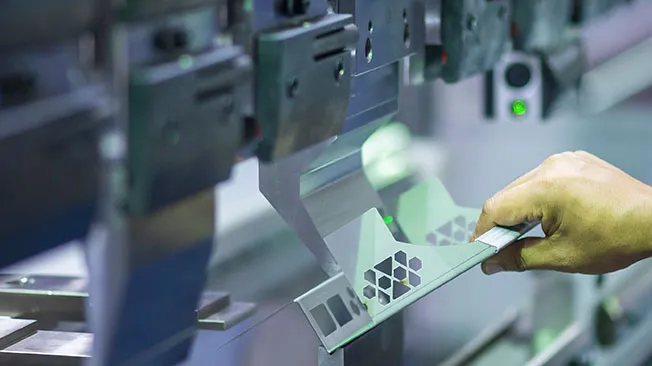
Sheet metal is one of the most common industrial building materials. Incredibly versatile and durable, sheet metal is used to create everything from aircraft to cars, architectural structures, consumer goods, furniture, civic infrastructure, and much more. It’s no exaggeration to say that sheet metal is one of the most crucial components of the contemporary world.
Strong, resilient, lightweight, and flexible, sheet metal is typically made of metal such as steel, aluminum, copper, brass, or tin that has been pressed into thin flat leaves, plates, or foils. Sheet metal is used for a wide range of various cladding and covering applications. Many industrial machines and domestic appliances are enclosed in sheet metal. Sheet metal is also used to create complex assemblies such as aircraft fuselage, vehicle chassis and bodies, frameworks for buildings, HVAC systems, and the hulls of boats.
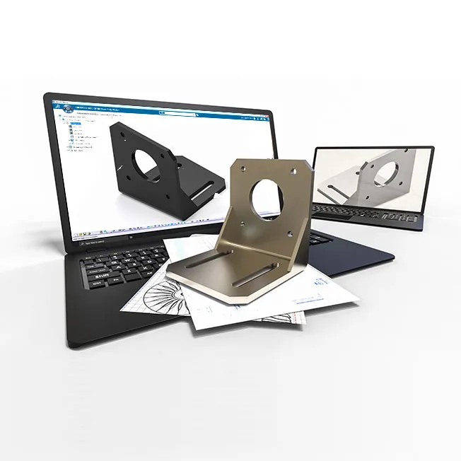
What is sheet metal design?
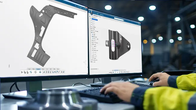
Sheet metal design is the act of creating a 2D drawing or a 3D model that is a digital visualization of an assembly, part, enclosure, component, or product. The design will contain the exact dimensions and specifications required to manufacture a part or product using the CNC machining process. These dimensions and specifications are converted from a CAD file into machine code and then fed into computers that control the CNC machinery.
Considerations in Sheet Metal Design
The sheet metal design process can be time-consuming and complicated. Sheet metal designers and engineers must take into account a wide range of factors when optimizing their designs, including considerations for tolerance. The thinness of sheet metal makes it ideal for a range of purposes, but also requires engineers and designers to be aware of sheet metal’s particular limitations.
Professional engineers who specialize in sheet metal box design and sheet metal enclosure design are often concerned with bending and forming the metal into desired shapes. While the elasticity of sheet metal makes it such a valuable material, this flexibility results in greater fragility which complicates the design process. Special care must be taken to precisely place holes, cuts, and bends as sheet metal is highly prone to shearing and tearing, especially when working with tight tolerances. Maintaining the uniform thickness of a piece of sheet metal is crucial to avoiding breakages and failures during manufacturing.
The importance of sheet metal design in manufacturing
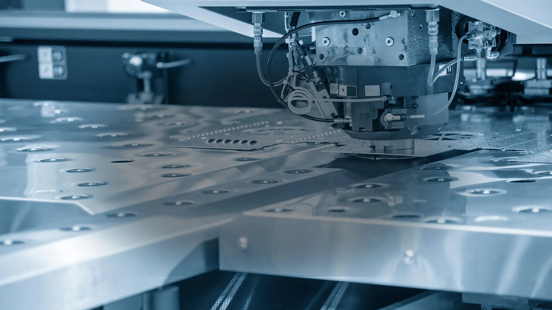
Sheet metal manufacturing can be done efficiently and economically on any scale using specialized computer numerical control (CNC) machining processes. CNC machining is done by cutting tools such as grinders, lathes, mills, and routers that operate on an assembly line to produce highly complex sheet metal products.
Instructions are given to the CNC machines via specialized computer programs. The cuts and shapes made by CNC machinery correspond exactly to the specifications outlined in a 3D CAD file. These files are created by skilled engineers or designers using sophisticated sheet metal design software. Every product made using sheet metal begins with a 3D drawing created by a talented sheet metal designer.
The basics of sheet metal design

The design for manufacturability principles
Sheet metal designers often use the principles of Design for Manufacturability (DFM). DFM dictates that any part, machine, structure, or product should be designed to achieve the most efficient and cost-effective manufacturing process possible. Concentrating on DFM principles helps designers to identify issues during the initial concept stages. In this way, design changes can be made early on that will minimize manufacturing costs and avoid the expense of having to rework designs once they have moved into production stages.
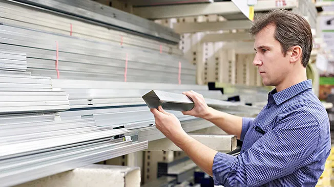
Material selection is crucial
When following DFM principles in relation to sheet metal design, engineers must first consider the thickness of the metal they will be working with. Material selection is a crucial step as this will determine how malleable the sheet metal will be, how fragile it may be, how durable it is, and how costly it is to acquire.
Once the material has been selected, designers must take into account the main operations that are involved in the custom sheet metal fabrication process.
Browse all the Dassault Systèmes store applications
We feature in our store some of our best software to design, collaborate and innovate throughout the entire product lifecycle.
Content related to sheet metal design
Basic sheet metal manufacturing operations
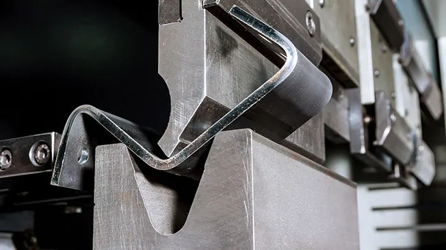
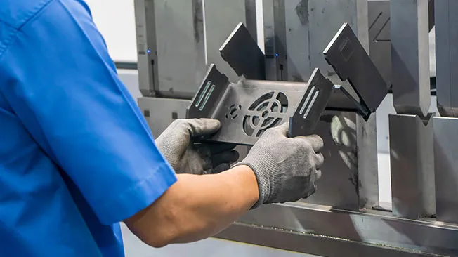
Bending
Bending involves the application of force at a certain point to form sheet metal around a straight axis. A piece of sheet metal is fitted over a die block and a punch piece is pressed into it, causing the workpiece to move into the die and form the desired shape. Two of the most common bending tools are bending brakes and brake presses. When designing sheet metal bends, designers must follow specific guidelines and consider critical factors such as the thickness of the sheet metal, the bend allowance, the k-factor of the metal, and the sheet metal bend radius.
Drawing
Sometimes referred to as deep drawing or cup drawing, this process involves a piece of sheet metal being stretched to form a concave or hollow shape. The sheet metal is placed over a die block and held in place with a blank holder. A u-shaped punch device is then used to force the sheet metal into the die so that it assumes the desired shape, ensuring that the material stretches to the minimum extent required.
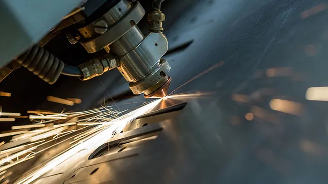
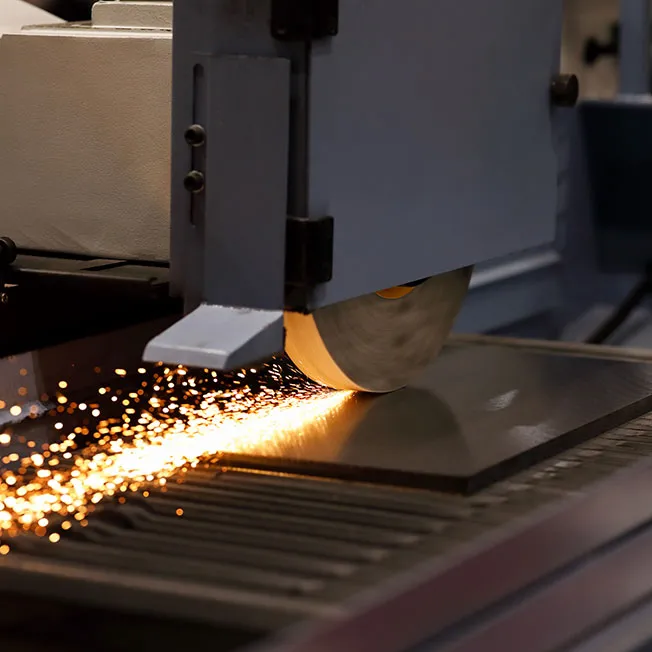
Cutting
Cutting is done to remove parts of a piece of sheet metal via shearing blades or die blades that are applied to the sheet metal using large amounts of force. As with bending and drawing, cutting using shearing blades or die blades is done by placing a piece of sheet metal between a die and a punch.
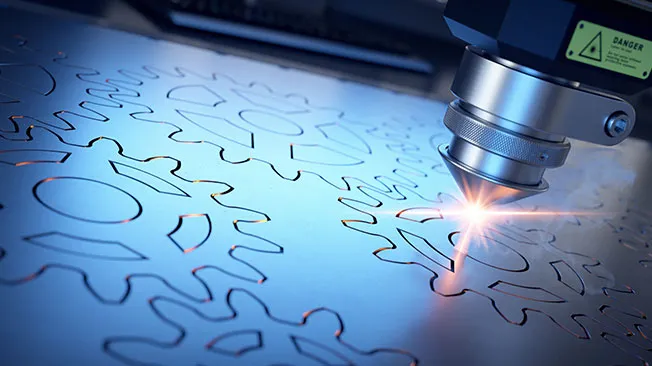
Sheet metal cutting is also often done using CNC-controlled CO2 lasers or fiber lasers. These lasers are able to cut through materials that are up to 20 mm thick, providing precision even for intricate designs. However, it's essential to consider the width of the laser beam when planning cuts, as it may affect the accuracy and efficiency of the cutting process. While laser cutting is highly economical and precise, it is not always suitable for certain types of sheet metal, for example some forms of aluminum sheet metal.
Finishing
Finishing is the process of adding a layer to the sheet metal to improve either its aesthetic appearance or enhance its functionality. Finishing sheet metal can be done using a variety of methods. Some of the most common finishing methods include applying coatings, such as paint or powder coating, polishing, plating, or anodizing. The choice of finishing method depends on factors such as the desired appearance, the intended use of the metal, and the turnaround times required. Some of the most common finishing methods include:
- Metal plating: Metal plating involves submerging the sheet metal into a chemical bath that alters the substrate surface by adding a thin layer of metal to it. This process is done to improve durability, improve corrosion resistance, and enhance the appearance of a product.
- Buff polishing: A cloth wheel is used to buff the surface of the metal, increasing its sheen, smoothness, and luster.
- Powder coating: Dry plastic powder is melted onto the surface of a piece of sheet metal to give it more texture or produce a glossier appearance.
- Sandblasting: Abrasive materials such as sand are forced onto the substrate at incredibly high speeds to smooth out the texture of the metal.
Other common sheet metal manufacturing techniques
There are also various other techniques of sheet metal manufacturing designers and engineers must also consider when creating a design using DFM principles. These techniques include:
The benefits of sheet metal design software
- Streamline the design process
- Enhance performance analysis
- Improve security and collaboration via the cloud
Streamline the design process
Sheet metal design software allows engineers and designers to develop better designs for optimum manufacturability capacity following DFM principles. Specialized CAD sheet metal design programs can automate many parts of the design process. These automated processes allow designers to fully manage and precisely emulate sheet metal rules through different design iterations. Making use of such functionalities streamlines the overall sheet metal design workflow and reduces production costs and time to market. Additionally, integration with advanced hardware such as 3D scanners and printers enhances the capability of these software solutions, enabling more accurate and efficient design iterations.
Enhance performance analysis
Advanced sheet metal development software can be used for performance analysis purposes. This capability removes the need to produce numerous physical prototypes and further reduces production costs and shortens manufacturing timelines. Sheet metal unfolding software allows designers to assess the stability of a design. Sheet metal bending simulation software can be used to accurately test various design iterations. 3D simulations can replicate the effect of real-world environmental stresses and component or material combinations on a design.

Improve security and collaboration via the cloud
The integration of cloud technology into sheet metal design software provides designers with more agility and allows them to collaborate remotely with colleagues at any stage of the design process. The cloud also provides a secure storage environment where files can be accessed and shared at any time, regardless of where colleagues or clients are located.
Explore Dassault Systèmes solutions
Discover the powerful browser-based modeling solutions from Dassault Systèmes. You can design whatever you wish, wherever you are with 3DEXPERIENCE.
Connecting data & people to foster innovation
The 3DEXPERIENCE platform on the cloud gives you access to a various set of applications that allow you to design, simulate, inform and collaborate on a project.
Sheet metal design, an overview
Sheet metal is used to build the vehicles we travel in, the buildings we live and work in, and the products we use. To develop complex designs that will lead to effective and durable products, designers and engineers need sheet metal design software that allows them to be agile, creative, and adaptable.
Dassault Systèmes continues to deliver innovative, intuitive, and powerful software that meets the unique requirements of sheet metal designers.
Why Choose Dassaut Systèmes for your sheet metal design needs ?
The power of the 3DEXPERIENCE platform
The 3DEXPERIENCE platform provides total design freedom as it allows you to securely store, share, and access files via the cloud. You can work on designs together with colleagues located anywhere in the world using any device at any time you choose.
The 3DEXPERIENCE platform enables users to collaborate on designs, share data, and manage revisions, making it easier for teams to work together and streamline the design process.


Continuing innovation in CAD software
Dassault Systèmes has continued to strive to produce powerful and versatile design software using cutting-edge technology, making it highly recommended for sheet metal design professionals. The suite of software solutions from Dassault Systèmes is transforming the way we design, simulate, manufacture, market, and use products and services.
First developed for use in the aviation industry, CATIA has become the software of choice for sheet metal design professionals across the globe. CATIA is unmatched in its ability to provide solutions specifically tailored for highly specialized design projects.