The Role of Sheet Metal Bends in Modern Manufacturing
Sheet metal bends are used by engineers and designers to create a huge number of different products, from airplanes to automobiles to electronics. Learn more about the different processes involved in sheet metal bending and just why it is so crucial to manufacturing.
What is sheet metal bending?
Sheet metal is sturdy, durable, corrosion-resistant, cheap, and highly flexible. Using mechanical processes, sheet metal can be transformed into a wide variety of shapes, making it an ideal manufacturing material.
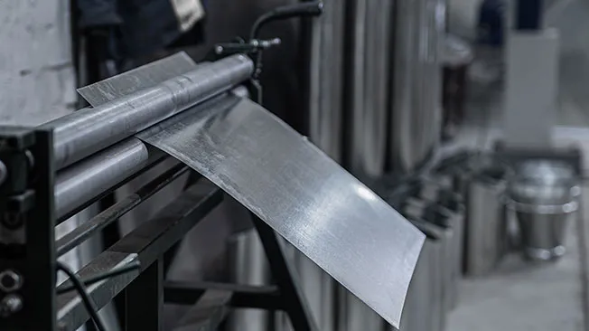
Sheet metal bends are created by applying force to a piece of sheet metal to change its shape. Applying force to a piece of sheet metal pushes it beyond its yield strength and makes it bend to the desired shape without losing any internal parameters or breaking apart. The thickness and length of the metal remain the same even after the bending process.
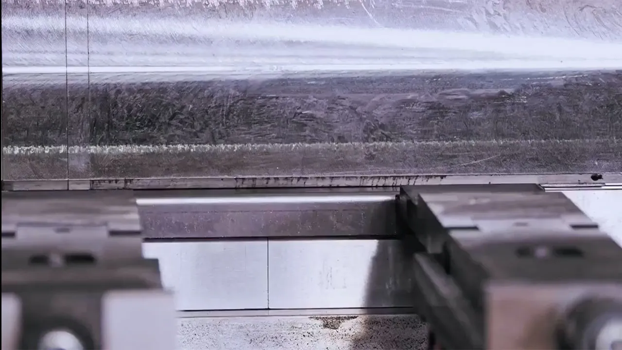
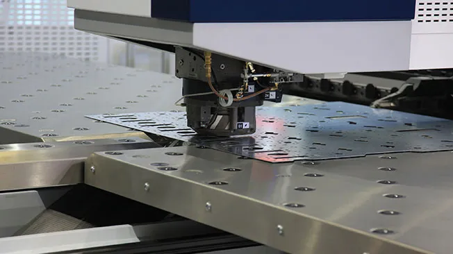
Sheet metal bends are usually made with CNC machining and metalworking tools such as a press brake. A press brake is used to create metal parts by pushing a punch into a piece of sheet metal positioned on a die. While this seems like a simple enough concept, sheet metal machining designs and processes can be complicated. Mechanical engineers must use sophisticated CAD software to create sheet metal design.
However, the role of a mechanical designer and a mechanical engineer in the process of sheet metal bending can be different. To understand more about their roles and responsibilities, you can visit this page.
Similarly, the role of an architect and a draftsman can also be different in the process of sheet metal bending. To understand more about their roles and responsibilities, you can visit this page.
Discover the Dassault Systèmes sheet metal design solutions
You can create highly complex sheet metal parts in 2D and 3D using CATIA Sheet Metal Designer from Dassault Systèmes. Take advantage of the amazing SOLIDWORKS Cloud offer and you can access leading sheet metal development software such as 3D Sheet Metal Creator.

SOLIDWORKS Design
From mechanical 2D or 3D design to manufacturing, accelerate your processes at an affordable price.
SOLIDWORKS xDesign
Get ready for the next generation of design solution, developed by the same team that brought you SOLIDWORKS 3D CAD
Common applications of sheet metal bending
The unique properties of sheet metal allow it to be used for a vast range of applications. Many industries use sheet metal bending techniques to create custom sheet metal parts and components. The malleability and versatility of sheet metal and the many ways in which it can be formed means that it is able to be used to produce both large assemblies on an industrial scale and limited runs of smaller, highly customized parts.
Sheet metal bending is widely used in the automotive industry to fabricate car bodies, frames, and panels. Engineers in the aerospace industry design airplane wings, fuselages, and various other aircraft parts using sheet metal bending. Ducts, vents, and other HVAC systems are made by forming sheet metal. As well as ventilation and heating systems, the construction industry also uses sheet metal bending to produce roofing, gutters, and many other building materials. Even the electronics industry uses sheet metal. Computers and sophisticated high-tech devices are commonly housed in sheet metal enclosures.

Understanding sheet metal bending processes
While the basic concept of sheet metal bends remains the same, there are many different types of sheet metal bending techniques. What technique is chosen will depend on the thickness of the metal, the sheet metal bend radius, and the exact part that is being fabricated. Let’s take a look at the most common sheet metal bending processes.
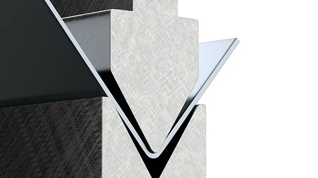
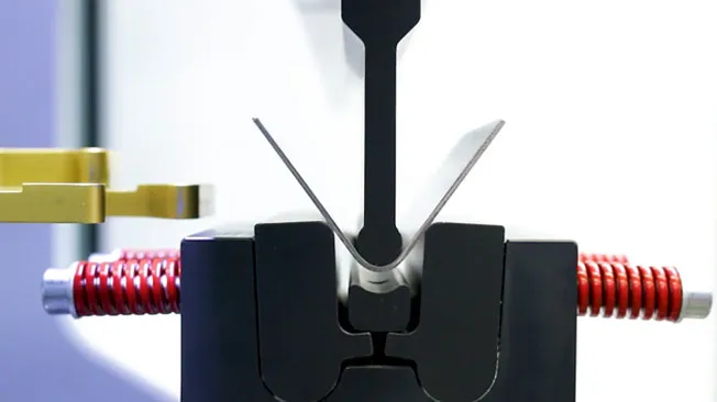
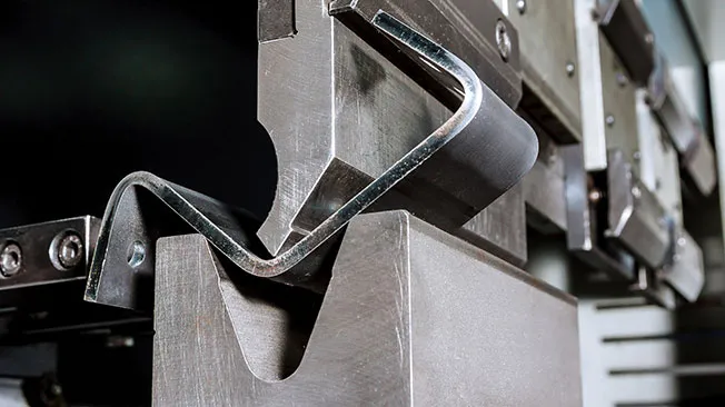
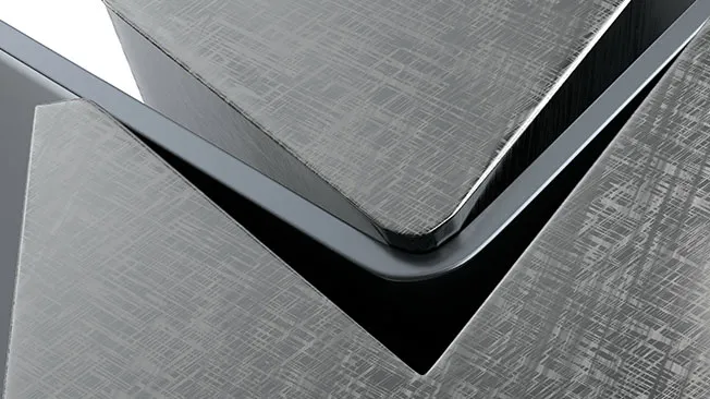
V-Bending
V-bending is the most commonly used metal bending technique. A v-shaped punch is lowered onto a piece of sheer metal that is laid across a v-shaped groove in a die. The punch forces the metal workpiece into the die creating obtuse, acute, or 90-degree angles.
U-Bending
U-Bending is much the same process as v-bending, except that the punch and die are u-shaped. This process is used to create sheet metal workpieces with rounded bends.
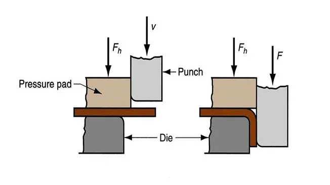
Edge Bending
Also known as wipe bending, the edge bending process works by forcing a punch downwards against a sheet metal workpiece held in place by a pressure pad. Instead of forcing the workpiece into a die, the punch moves (or wipes) the sheet metal down over the edge of the die to create a bend.
Air Bending
Air bending is a form of v-bending. Unlike the v-bending method, air bending does not force the workpiece into the very bottom of the die. It leaves a gap between the bottom of the workpiece and the die cavity. Air bending allows for more control over the bend angle.
Bottoming
Also referred to as bottom bending, bottoming is a v-bending technique used to solve issues of springback. When using a bottoming technique, additional force is applied to the die after the bend is complete.
Coining
Coining stamps the workpiece between the punch and the die as with v-bending. However, the coining technique involves having the punch penetrate the workpiece, just like coins are imprinted when they are being minted.
Rotary Bending
Rotary bending is sometimes called rotary draw bending. In this process, the workpiece is held by a rotating die and then drawn around the die to form the desired bend. There is often a mandrel that provides internal support and stops the workpiece surface from wrinkling. Rotary bending does not scratch the surface of the workpiece, unlike other sheet metal bending techniques.
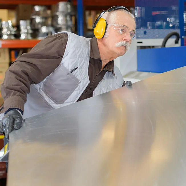
Tools and equipment used in sheet metal bending
Browse all the Dassault Systèmes store applications
We feature in our store some of our best software to design, collaborate and innovate throughout the entire product lifecycle.
Content related to sheet metal bends
A step-by-step guide to the sheet metal bending process
The first step in the sheet metal bending process is to create a design that can be used either by CNC machinery in an automated process or by engineers to manually bend the metal. Sheet metal designs are created using specialized CAD sheet metal unfolding software. An engineer may also create a 3D model that can be used to run a sheet metal bending simulation.
Often, the sheet metal workpieces will need to be prepared before bending. The metal may need to be cut into certain lengths, sheared, punched, or stamped. An engineer will need to carefully evaluate the thickness of the metal to determine the bending sequence and the angles required. To do this, they need to calculate the k-factor and the y-factor of the workpiece. These calculations are used to evaluate the bend allowance of the material.
Next, the tooling and equipment required will have to be selected. The machinery selected will depend on the nature of the finished product, for example, a press brake with a v-shaped punch and die for v-bending. The sheet metal then needs to be loaded and clamped into the machinery before the bending process can begin. Once completed, the sheet metal is unloaded and inspected for faults or defects.

Factors that impact sheet metal bending
Engineers need to consider a range of factors when designing sheet metal bends. The material type and the thickness of the material are crucial to calculating the bend allowance. Engineers also need to be sure they use a single bend radius as this will reduce the need for extra tooling work. The bend radius must be equal to or gather than the thickness of the sheet metal workpiece.
The tooling selection is also critical. Choosing the right type of machinery will help to avoid issues such as springback, which is where a workpiece will revert partially or wholly to its original form after the bending process. Air bending, for instance, results in less springback than simple v-bending.
Why use a CAD solution for sheet metal bending?
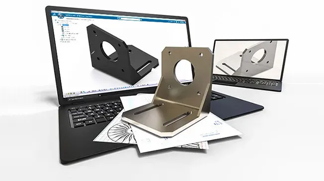
To produce quality parts, an engineer must create a highly accurate sheet metal design. Using CAD sheet metal development software ensures that there are no small errors in the design that can become major issues during fabrication. Dedicated sheet metal design software results in clearer, highly detailed plans that can be converted into CNC files.
CAD sheet metal designs ensure there are fewer inaccuracies in design interpretation at the shop floor and vendor levels. By using a CAD sheet metal bending simulation there is less time lost in revisions and no need to repeatedly fabricate physical prototype parts.
Explore Dassault Systèmes solutions
Discover the powerful browser-based modeling solutions from Dassault Systèmes. You can design whatever you wish, wherever you are with 3DEXPERIENCE.
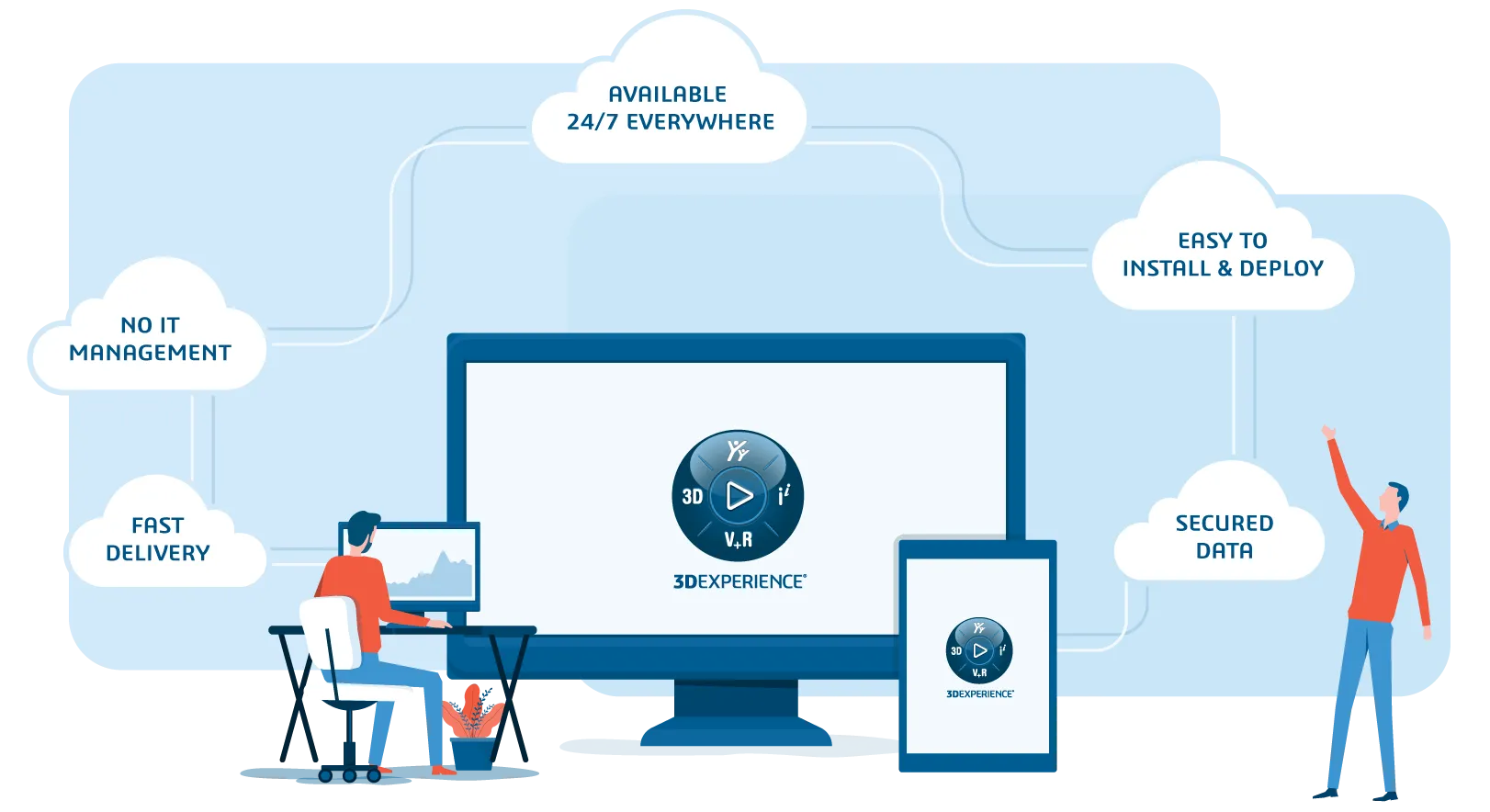
Connecting data & people to foster innovation
The 3DEXPERIENCE platform on the cloud gives you access to a various set of applications that allow you to design, simulate, inform and collaborate on a project.
The best CAD solution for sheet metal design software
CATIA Sheet Metal Designer is an innovative, powerful CAD software that provides professionals with an essential solution for sheet metal bending. Using CATIA Sheet Metal Designer you can have a real-time view of the design so all changes can be tracked accurately. CATIA Sheet Metal Designer can be seamlessly integrated with other PLM and CAM software. The revolutionary 3DEXPERIENCE platform is a cloud solution that provides you with a digital collaborative design environment.
Sheet metal bends - Conclusion & Perspectives
Sheet metal bending is a fabrication method that is essential for major industries. The ability to accurately form sheet metal into precise components is crucial for sectors such as the automotive, aerospace, construction, and electronic industries. Sheet metal bending is used to produce the vehicles we travel in, the computers we use and the houses and offices we live and work in.
To ensure that quality products are produced, engineers must use powerful sheet metal forming software. CAD 3D modeling tools can create highly complex sheet metal designs for large assemblies and small custom parts. Engineers can use these tools to view their designs in both folded and unfolded views and to run simulations, thereby ensuring optimum manufacturability.
Why choose Dassault Systèmes for your sheet metal design needs?
The power of the 3DEXPERIENCE platform
The 3DEXPERIENCE platform is unlike any other cloud-based software on the market. This innovative tool provides users with a uniform digital environment that can be accessed by any team member at any time, anywhere on the globe, using any type of device.
Users can harness the power of cloud computing to run a complete range of Dassault Systèmes’ CAD solutions.

Benefit from more than 40 years of experience
Dassault Systèmes draws on more than 40 years of CAD experience to deliver effective solutions for sheet metal designers and engineers. Our background in the aerospace industry means we know exactly what designers and engineers need. We strive to constantly refine our roles to provide ever more powerful, more innovative, and more creative software. Discover how far your ideas can go with Dassault Systèmes. Visit our online store and explore our range of roles today.