What is NURBS modeling and why is it crucial to CAD software?
Anyone that has had some experience with 3D design software has probably used NURBS modeling. Join us as we take a closer look at NURBS curves and surfaces and why they are such an important part of 3D designing software.
What are NURBS curves in 3D modeling?
Despite the odd name, NURBS curves and surfaces are a hugely important feature in parametric 3D modeling. NURBS curves are mathematical representations of curved shapes in three dimensions.
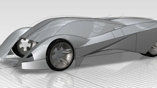
Using NURBS modeling, engineers and designers can create rounded shapes with gradual slopes and organic forms. NURBS modeling uses complex mathematical equations to create realistic circles, arcs, and 2D surfaces that are used to draw flexible, accurate, and highly lifelike 3D models.
The rather strange acronym NURBS stands for Non-Uniform Rational B-Splines Modeling. The Non-Uniform part denotes that NURBS can be used to create freeform shapes. That is, you can manipulate the geometry to form whatever you want, instead of relying on set parametric shapes.
The word ‘rational’ is used to denote how NURBS evaluates and prioritizes the perceived weight or effect of each control point on the curve itself in a non-homogeneous manner. A simple B-spline cannot be used to create parabolic shapes as it must follow a uniform distribution between control points.
That B denotes the word ‘basis’. Splines are used in 3D design software to create vector works and polylines. A spline is a curve that travels along a continuous path mapped out by anchor points and control points. This process is a crucial part of mechanical design and is often the responsibility of a mechanical designer or engineer.
Explore powerful NURBS modeling solutions at the Dassault Systèmes store
Dassault Systèmes proudly stands at the forefront of 3D design software. For decades, industry professionals across a wide range of sectors have relied on us to provide them with powerful, highly sophisticated 3D modeling software.

PLM Express Design Engineering
Empower smart product design and boost engineering precision

SOLIDWORKS Design
From mechanical 2D or 3D design to manufacturing, accelerate your processes at an affordable price.
What are splines and why are they important in NURBS modeling?
The concept of splines in 3D modeling can be hard to grasp. Originally, splines were flexible wooden strips that were used to provide an outline that designers could trace when designing curves for airplanes and boats.
Splines work using control points in NURBS modeling. The control points in NURBS modeling act to define a curve by a process called ‘interpolation’. NURBS modeling sets the control points and performs mathematical equations to average out the distance between each point.
Instead of using thousands of tiny dot points to draw a curve, the computer takes a few control points, assesses the position and rotation of each handle, and creates a continuous smooth curve. Moving any of the control points will create a new curve. Splines are an essential component in freeform modeling. Curves created with splines are highly complex. They are not as likely to warp or distort applied textures.
The historical background of NURBS modeling
The first recorded use of B-splines is credited to Russian mathematician Nicolai Ivanovich Lobachesky all the way back in the 1800s. The birth of modern spline theory happened in 1946 when a Romanian- American mathematician called Isaac Jacob Schoenberg released a paper on data approximation.
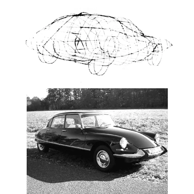
B-splines were further refined throughout the 1970s by mathematicians M.G. Cox and C. de Boor. Cox and Boor independently invented algorithms that extended the famous de Casteljau algorithm, which was used by famed designer Pierre Bézier to develop the iconic curves of the Citroën DS. Further research by W. J. Gordon and R. Riesenfeld proved that Bézier curves were subsets of B-splines and outlined the powerful possibilities of B-splines for design.
The breakthrough came in 1979, when Ken Versprille of Syracuse University, New York, published a Ph.D. thesis on Rational B-Splines–NURBS=Non-Uniform Rational B-Splines. Versprille’s revolutionary design theories were soon developed into workable code by the tech company Computervision. Soon after, NURBS were taken up by the aerospace giant Boeing and used in their CAD program TIGER. NURBS are now an integral design tool and can be found in every CAD modeling program.
What industries use NURBS modeling for design?
NURBS modeling is used for a wide variety of applications. Many universities teach NURBS geometry as part of computer science or mathematics degrees. NURBS modeling is used for any instance where a designer or engineer is required to create an accurate and lifelike digital representation of a real or theoretical physical object.
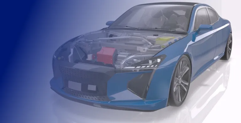
The ability of NURBS to create smooth, realistic contours that can be made even more lifelike by adding textures means that it is commonly used in product development, for the aerospace and automotive industries, in architecture, manufacturing, and in mechanical engineering. NURBS are also widely used in CGI imagery and 3D animations.
How NURBS modeling relates to other modeling techniques
NURBS modeling, polygonal modeling, subdivision modeling, and parametric 3D modeling are all common methods of creating CAD models and designs. While there are certainly similarities, there are some significant differences between these techniques.
Polygonal modeling and NURBS modeling
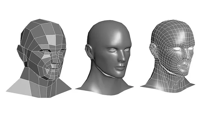
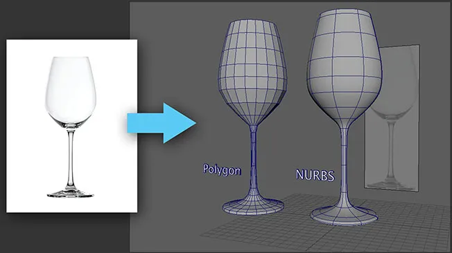
NURBS modeling uses control points that are connected by splines to create curves. Polygonal modeling works by meshing thousands of flat triangular planes to create a shape. You cannot easily create a perfectly smooth curve using polygonal modeling as the computer always calculates polygons as a straight line between two control points.
To create a curve using polygonal modeling, a designer must use smoothing groups and huge numbers of polygons grouped together. This then appears as a smooth curvature when viewed on a screen. However, polygonal modeling is not suitable for manufacturing as CNC tools require a perfectly smooth curve in order to create quality products. Only NURBS modeling can achieve this.
Subdivision modeling and NURBS modeling
Subdivision modeling creates a 3D mesh that can be manipulated in any manner the user wishes via a push-and-pull method. Also known as SubD, subdivision modeling is better suited to organic shapes that do not have to be particularly precise. As such, SubD modeling is more often used for 3D rendering animations for movies and video games.
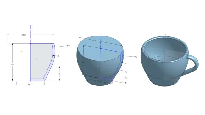
Parametric modeling and NURBS modeling
Parametric modeling is based on NURBS modeling techniques. A parametric model will automatically update whenever a dimension is changed. There is no need for the designer to keep redrawing the model, unlike the freeform method of SubDmodeling.
NURBS modeling techniques
The basics of NURBS modeling techniques with CAD software include functions such as:
- Curve Creation
- Surface Creation
- Surface Editing
Curve Creation
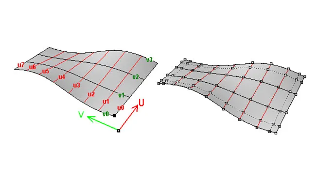
Control points are set within a digital 3D space, a curve degree is set and the program creates a NURBS curve based on these parameters.
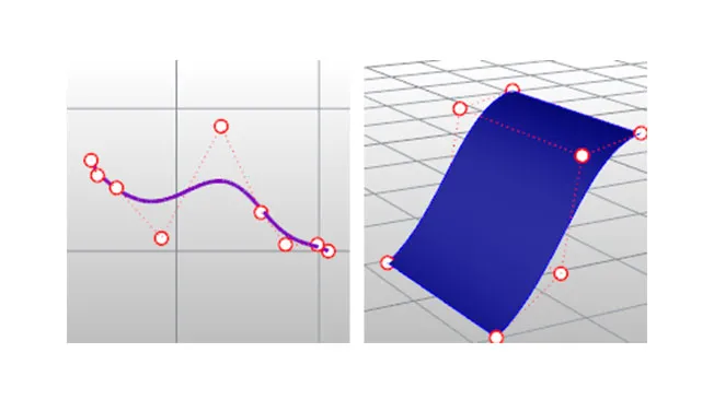
Surface Creation
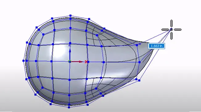
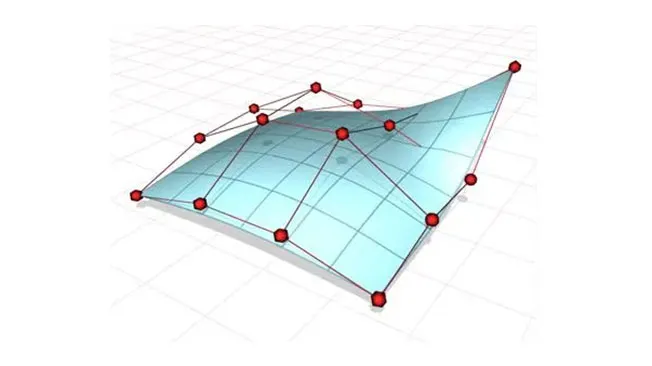
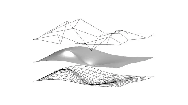
A NURBS surface is created by compiling a mesh of weighted control points.
Surface Editing
Each control point on a NURBS surface has a ‘weight’ attached to it, meaning that it can be manipulated to ‘pull’ the surface towards it.
Browse all the Dassault Systèmes store applications
We feature in our store some of our best software to design, collaborate and innovate throughout the entire product lifecycle.
Content related to nurbs modeling
Advantages of NURBS modeling
The biggest advantage of using NURBS is that they allow designers to create an absolutely smooth curve. The mathematical algorithms that are used to create NURBS curves mean that the surfaces are completely smooth regardless of how closely the shape is examined.
NURBS modeling allows for much greater precision and control compared to other techniques. This is why it is so often used for product design and for the design of automotive chassis and airplane fuselages.
The lower polygon counts involved in creating NURBS curves and surfaces require less computing power, so they are more lightweight and can be used to create 3D models in less time than other methods.
The limitations and challenges of NURBS modeling
Although there are many benefits to NURBS modeling, the technology does have drawbacks and limitations. NURBS are much more suited to hard surface models such as commercial products or vehicles that have rounded surfaces. Many designers and engineers experience difficulties with creating sharp edges and corners using NURBS.
NURBS software often has a steeper learning curve than SubDor polygonal modeling software. For this reason, users require a higher level of expertise to work with NURBS. Often, a designer or engineer must have a solid understanding of the complex mathematical principles behind NURBS in order to achieve their desired results.
Nurbs modeling - Conclusion & Perspective
NURBS modeling uses complex mathematical equations to depict curvatures and sloping inclines. NURBS modeling is a highly useful CAD tool used to create highly realistic 3D rendered models of objects that have rounded shapes. It is mostly used for automotive and aeronautical design but is also widely used for CGI effects in film and in 3D animations.
The development of NURBS represented a dramatic breakthrough in CAD technology. NURBS allowed designers to create highly detailed complex shapes that had perfect curvatures. It is ideal for product development purposes. NURBS modeling is also essential for CNC processes since polygonal molding does not result in perfectly curved lines and therefore cannot be used by CNC machining tools.
If you are interested in any type of CAD design work, then you need to familiarize yourself with NURBS modeling techniques. While NURBS modeling is not suitable for every type of CAD application, the wide breadth of uses that it does have makes it a crucial knowledge point for any designer or engineer.
Why choose Dassault Systèmes for your 3d modeling needs?
Take advantage of the power of the 3DEXPERIENCE platform
The 3DEXPERIENCE platform gives you access to a massive range of Dassault Systèmes’ powerful design software and PLM solutions. Users can access incredibly versatile and effective software powered by the cloud, instead of having to invest in expensive systems themselves. You can pick and choose exactly what you need and access the software from any location, on any type of device.
The 3DEXPERIENCE platform allows you to share and collaborate on files using specialized solutions such as 3D Creator and Sculptor and CATIA Mechanical Designer. Reinvent the way you develop and manufacture products. Step into the future of design with the 3DEXPERIENCE platform.

Take your ideas to the next level with Dassault Systèmes
With more than 40 years of experience, Dassault Systèmes is an industry leader in product lifecycle management (PLM) software. The powerful CAD solutions from Dassault Systèmes have given engineers and designers the ability to push their ideas further and innovate and create like never before.
From the revolutionary CATIA design software to the current online CAD modeling solutions contained in the SOLIDWORKS cloud offer and the 3DEXPERIENCE platform, Dassault Systèmes has always been at the forefront of product development, engineering, and manufacturing.