Designing a Stealthier Submarine with Design-driven Simulation Tools
How MODSIM enables the development of modern undersea defense technology, using stealth design as an example of the benefits of a MODSIM approach.
Stealth and detectability are a critical aspects of the design of a submarine. The radar cross-section (RCS) of a submarine at the surface depends not just on the geometry of the vessel, but also the hydrodynamic wake on the water surface. Simulation can be used to analyze the RCS of a semi-submerged submarine in motion, and to optimize the geometry to minimize the RCS of the wake. A unified approach to modeling and simulation (MODSIM) allows the simulation results to inform the design, shortening the development process to produce a submarine that achieves stealth requirements without compromising other objectives.
Introduction
Submarine engineering is a challenge – there are few areas of engineering that require such precise control of as many different domains of physics. A successful, safe and reliable underwater vessel design must be able to withstand the pressures of deep ocean water and the stresses of waves – and the shock impacts of combat. It must travel with minimal drag as silently as possible while also minimizing its radar cross section. Its hydraulic, electrical, thermal, ventilation and mechanical systems are safety-critical and all need to operate reliably for months on end.
This means submarine development requires large teams with many different specialist groups working together to produce a fully capable vessel that can carry out undersea defense objectives.
This blog post will demonstrate how MODSIM, unified modeling and simulation, enables the development of modern undersea defense technology, using stealth design as an example of the benefits of a MODSIM approach.
Hydrodynamics and Radar
The detectability of a submarine depends on several factors. The noise signature of a submarine affects how readily the vessel is detected by passive sonar. The sound is not just a result of vibrations and noise from machinery inside the vessel – the hydrodynamical design of the hull itself affects noise as water flows turbulently, particularly around control surfaces. A poorly optimized design produces excess noise and increases the vessel’s detectability.
Another important factor is the radar cross section (RCS). When radar waves strike the vessel, they are reflected and scattered. The waves that are back-scattered towards the receiver are what allows an enemy to detect the submarine. Therefore, one of the basic principles of stealth design is to minimize the back-scatter. For undersea vessels near the surface, this is further complicated by hydrodynamics as the wake produces a complex free surface deformation pattern.
To maximize stealth, we need to be able to deal with both these effects at the same time. This means naval architects, radar engineers and computation fluid dynamics (CFD) experts all need to work together in a multi-domain, multi-objective workflow.
Stealth Design Workflow
Modeling the submarine
The workflow to reduce detectability begins early in development. The sooner stealth factors are considered, the less risk there is of problems being found late in testing, and the more potential there is to find an optimal solution. As soon as the initial CAD model of the hull is available, work can begin.
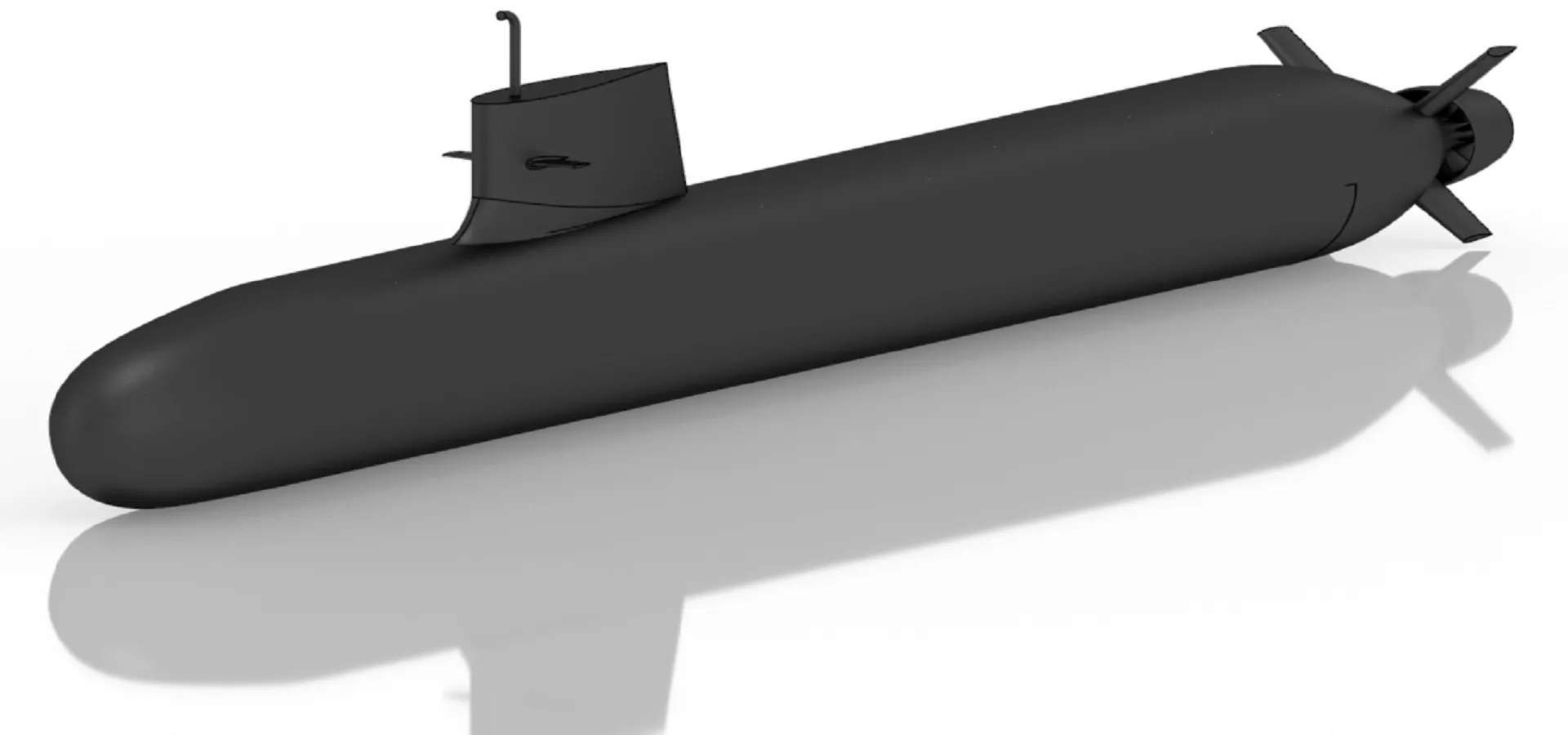
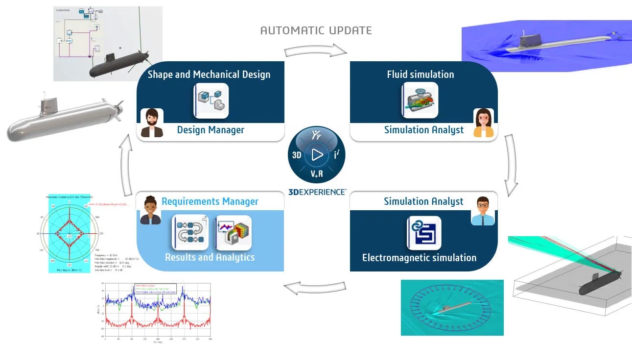
The project begins by making full use of the “Requirements, Functions, Logical and Physical” (RFLP) data model to build the CAD model shown in Figure 1. The model geometry was built with CATIA roles, with parameters allowing optimization later, and therefore it can be made immediately available for simulation on the 3DEXPERIENCE platform. The CAD model is more detailed than is needed for the simulation, so automatic de-featuring increases simulation performance.
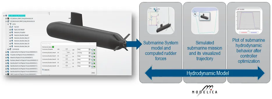
The submarine system’s dynamic behavior is modeled and simulated using the Dymola Behavior Modeling (DBM) application, which is an integrated 1D-modeling and simulation environment on the 3DEXPERIENCE platform. DBM directly generates multibody system models from CAD data and provides 3D visualization and animation capabilities of the system behavior. This is used to generate a multibody model of the submarine including control surfaces. With this, users can study the hydrodynamic behavior of the submarine under varying operational conditions or drive strategies. The control systems of ballast tanks can be accurately modeled, in order to realistically represent surfacing and diving behavior. Different drive units – for instance, diesel engines or fuel cells – can also be considered in the simulation. Above described process is fully summarized in Figure 2.
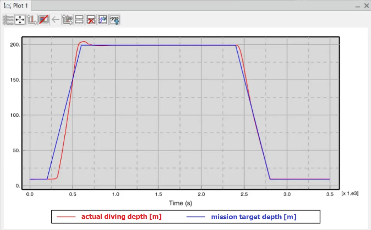
The results of the control system simulation are compared with the test requirements (see Figure 3). If they are not met, the model parameters and topology can be modified through an iterative process until the target behavior is achieved.
Modeling the Wake with Computational Fluid Dynamics
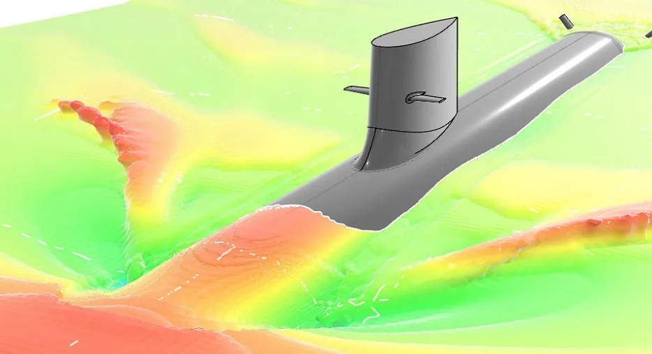
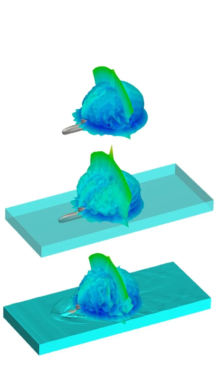
Once we have the geometry and control surfaces optimized, we can calculate the hydrodynamic wake of the submarine. We use the SIMULIA Fluid Dynamics Engineer, which takes advantage of a state-of-the-art unstructured second order fully implicit finite-volume Reynolds-Averaged Navier-Stokes (RANS) solver to model the flow, including turbulence. The interface between water and air, where the surface wake forms, is solved using the multiphase Volume of Fluid (VOF) formulation. The free surface VOF iso-contour plots are the data we need for the next stage of the simulation. Figure 4 shows an example from the semi-submerged submarine.
Any flow simulation requires careful meshing, as this affects both convergence behavior – which determines the speed of the simulation – and the accuracy of the results. Under MODSIM, meshing is a largely automated process.
Analyzing RCS with Electromagnetic Simulation
For this simulation, we used a shooting-and-bounding ray (SBR) model with the Asymptotic Solver in Computer Simulation Technology (CST) Studio Suite. The SBR method has been demonstrated to be effective and accurate for simulating large structures. The CST Studio Suite SBR method includes shadowing and multi-path effects as well as Physical Theory of Diffraction (PTD) and Uniform Theory of Diffraction (UTD) for greater accuracy, making it an effective electromagnetic tool for Radar Cross section (RCS) evaluation and for the generation of radar signals in maritime environments.
The free-surface VOF iso-contour plots are directly translated into a tessellated mesh from the Fluid Dynamics Engineer (FMK) app into CST Studio Suite through the 3DEXPERIENCE platform. This provides the single source of truth, collecting all the different modeling and simulation data, as well as the Requirement, Functional, Logical & Physical framework (RFLP), in a single place accessible to all team members. Everyone has access to the latest versions of all files, reducing the risk of confusion and delays caused by using different versions of data or incompatible file formats. Traceability is preserved across different design iterations. These processes result in the overall radar signature workflow description as highlighted in Figure 5.
To calculate the RCS, a monostatic scattering simulation is carried out along the azimuth angle from 0 to 360 degrees, with a 0.1 degree step width at a fixed elevation angle of 1 degree (almost sea level). In other words, the radar scattering is calculated at each azimuth angle around the sweep, and plotted in 1D around the target, which in this case is the portion of the submarine above the surface of the sea. The sea itself is not the target but since we wish to observe the effect of the sea on the RCS of the submarine we must include the sea in the simulation. Conventional radars identify the direct reflections from the sea as clutter and automatically cancel such reflections so that the RCS of the periscope can be isolated still including the sea effect. The same is done in simulation.
Figures 6 and 7 show the RCS of the complete submarine – a full 3D far-field has been plotted here for illustrative purposes.
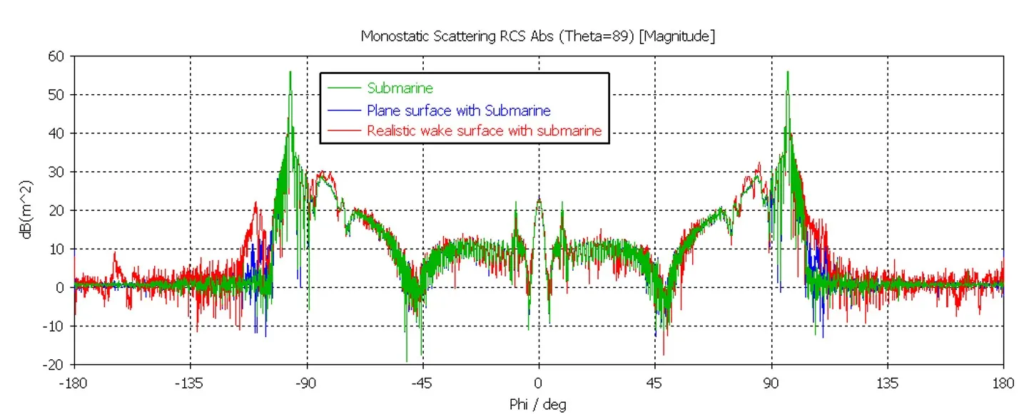
The results show that adding an ideal block of seawater changes the RCS of the submarine, and replacing this block with a realistic volume of sea with the wake further changes this RCS thus improving overall accuracy.
Simulation-led Design and Optimization
Conventional submarines use periscopes and snorkeling masts as vertical appendages to approach and breach the free surface. This means that these are a major source of hydrodynamic disturbance and turbulence. This results in an unsteady flow and a high, steep bow wave at snorkeling speeds below 5 m/s. This wave can be identified by radar or visual observation. To address this issue, baffles are added to the periscope – in this case, a helical strake running up the periscope disrupts the development of the bow wave (Figure 7). The strake model is parameterized so the thickness and pitch of the helix can be varied for a component optimization study.
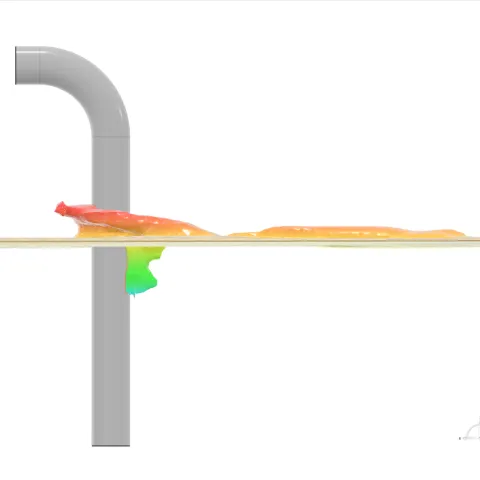
Figure 8: Side-view of the free surface elevation for the (top left) isolated periscope at Fr = 1.3, (top right) isolated periscope at Fr = 1.8, (bottom left) periscope with 150 mm helical strakes at Fr = 1.8, (bottom right) periscope with 300 mm helical strakes at Fr = 1.8
Most submarine manufacturers are interested in improving stealth only from the front, because it is only when the submarine enters the territory of an enemy that stealth becomes a crucial requirement. When the submarine retreats, stealth might not be of as much importance. Hence the angular range of interest in the azimuth plane can be assumed to be from -80 to +80 degrees. This has been highlighted in figure 9, which shows how the RCS changes when modifications are made to the periscope of the submarine. The addition of helical strakes, especially at 300 mm, significantly reduced the RCS in the range of interest. Because a MODSIM methodology has been used, the optimized periscope design from the simulation can be easily returned to the model and integrated into the final submarine design.
Conclusion
MODSIM, unified modeling and simulation, enables engineers to develop cutting-edge designs faster and more efficiently. For an undersea defense vessel, MODSIM enabled a full RCS analysis for stealth purposes, covering multiple physical disciplines. The unification of CAD and CAE meant that the submarine design data could be easily converted into a simulation-ready model, and the integration of different simulation tools on the 3DEXPERIENCE platform allows systems, electromagnetic and fluid simulations to be combined into a single workflow to accurately capture the complex interaction of radar scattering and hydrodynamic wakes. Using MODSIM, the engineers were able to find an optimal periscope geometry quickly, reduce RCS and improve stealth, and implement this in the final design.
The defense industry is moving towards model-based acquisition. This requires a digital transformation in the acquisition process, with new and collaborative ways of working between defense agencies and their suppliers. Find out more on designing and engineering next generation naval defense platforms with the 3DEXPERIENCE Platform.