Submarine Fluid Simulation: Hydrodynamics, Propeller Dynamics and Wake Tracking
Submarines pose several unique engineering challenges, distinct from surface vessels. Simulation helps naval engineers design submarines with reduced drag, improved performance, and lower detectability.
In this article, we show how simulation can enhance submarine hydrodynamic performance by optimizing efficiency, reducing drag, and analyzing acoustic effects and wake tracking. We demonstrate workflows in SIMULIA PowerFLOW for analyzing submarine hydrodynamics throughout development on the DARPA SUBOFF benchmark. We will show how hull drag and propeller performance can be analyzed both in isolation and installed, with excellent agreement between benchmark measurements and simulation data.
Why Simulate Submarines?
Computational Fluid Dynamics (CFD) models fluid flow and fluid-structure interaction. The marine and offshore industry widely uses CFD simulation to design and analyze ships, submarines, and offshore structures.
CFD can be used to model the hydrodynamics and drag of the vessel. The flow of water around the hull includes areas of turbulent flow, especially around sharp corners and edges. Also, the boundary layer, dependent on the Froude number, is typically turbulent. Turbulent flow is chaotic and difficult to calculate. One powerful approach for modeling turbulence is simulation using the Lattice Boltzmann Method (LBM). SIMULIA PowerFLOW uses LBM with a Very Large Eddy Simulation (VLES) approach. This models fluid flow around large geometries efficiently while still capturing turbulent flow details.
Submarine engineering requires special design considerations. Submarines need control surfaces: rudders, fins, and diving planes. These surfaces allow three-dimensional movement, similar to an aircraft. Just as aerodynamics is crucial for ensuring the maneuverability of aircraft, hydrodynamics is needed to ensure safe, efficient submarine control. Simulation allows engineers to optimize control surface design and streamline the hull to reduce drag.
Many submarines are built for naval applications, where stealth is a primary objective. The military value of a submarine comes from its ability to move underwater without detection. Deep underwater, where radar waves do not penetrate, the detectability of a submarine is largely determined by its interaction with the water around it. Propeller cavitation effects can generate considerable noise, as well as its turbulent wake. This noise can propagate for many miles in the water. Acoustic solvers in SIMULIA PowerFLOW can model noise propagation in water without the need to combine different simulation tools.
A submarine also leaves a telltale wake, a trail of disturbed, turbulent water that can be detected behind it and can even cause waves visible from the surface. The powerful, efficient LBM-based solvers in SIMULIA PowerFLOW can model wake propagation for an extended distance behind the submarine, helping engineers find solutions to minimize the residual wake turbulence.
SIMULIA PowerFLOW is part of the wider Dassault Systèmes portfolio, which also includes design tools such as CATIA on the 3DEXPERIENCE platform. Unified modeling and simulation (MODSIM) breaks down the silos between designers and analysts, enabling designers to evaluate how their designs will perform without building and testing physical prototypes. This streamlines development, lowers costs and minimizes risk.
Submarine Hydrodynamics Workflow
Hull resistance
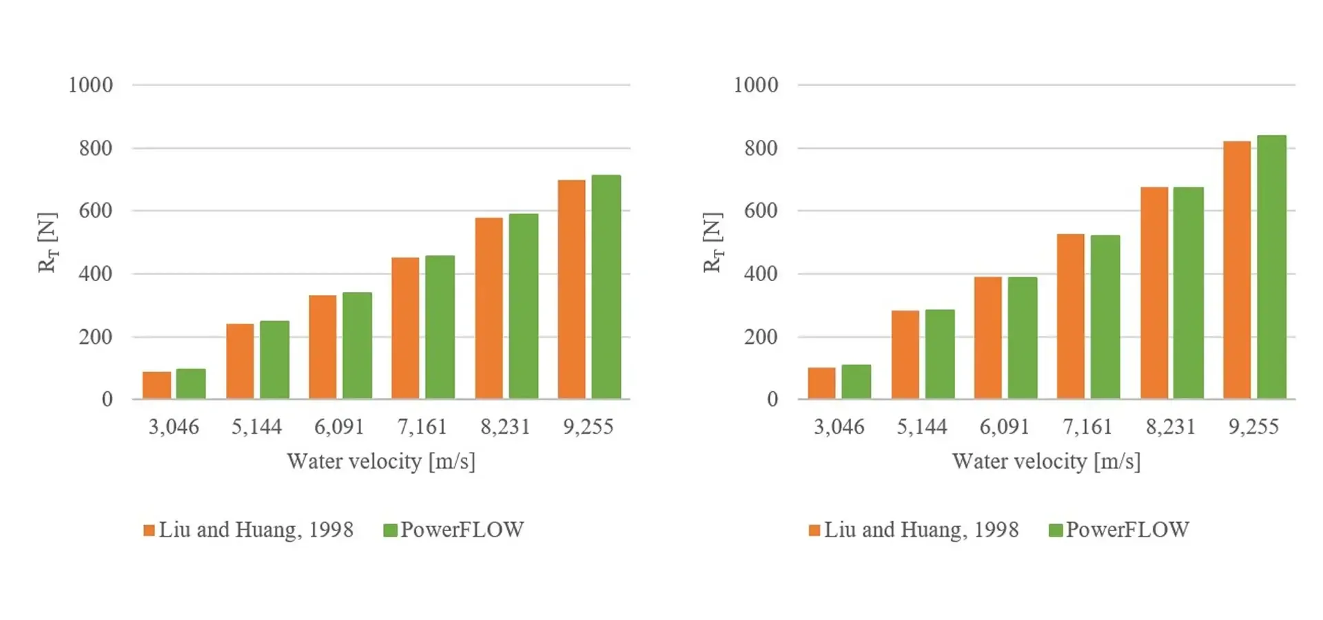
Hull resistance can be analyzed both in terms of the bare hull and the full assembled vessel with appendages such as diving planes and the sail fin. In the SUBOFF benchmark, the bare hull is labeled AFF-1 and the hull with appendages as AFF-8. The first study was to calculate total resistance. As shown below, excellent agreement was found between measured and simulated data for all water velocities.
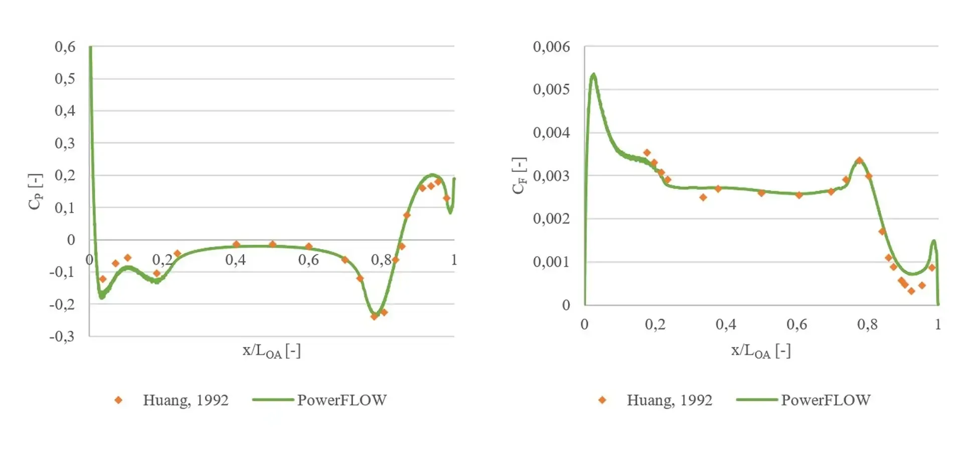
With the accuracy verified across all water velocities, we can now analyze the pressure distribution and skin friction along the hull. This will capture localized effects such as drag around the nose and the impact of the diving planes. The simulation shows excellent agreement. We observe this particularly around the submarine's nose, where both the peak value and slope are precisely predicted.. This indicates that the simulation effectively captures key boundary layer characteristics, including its size and transition location. These results reinforce the reliability of the simulation in reproducing critical local flow phenomena.
Open water propeller performance
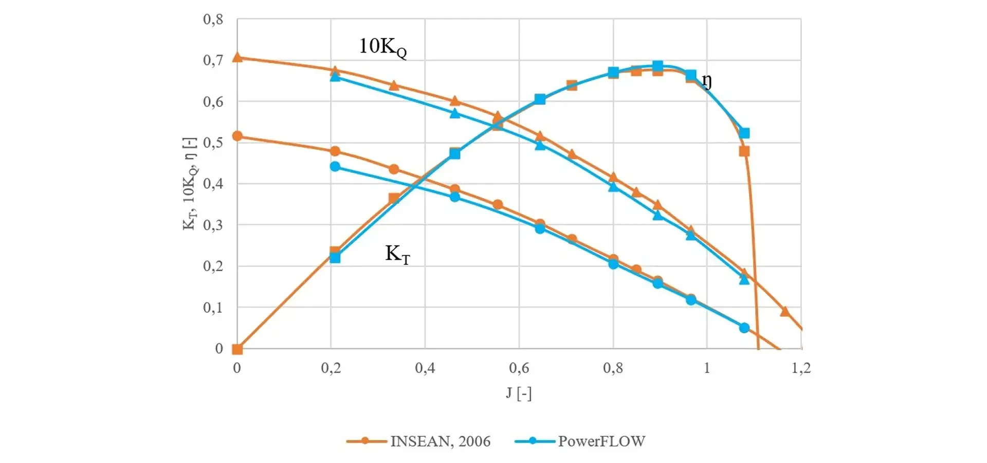
In addition to validating hull resistance, this study also examines the performance of the propeller both in isolation and when installed. For a full description of the propeller simulation workflow, using the INSEAN E1619 propeller benchmark, see our blog post “Validating underwater propeller performance with SIMULIA PowerFLOW”.
In general, the propeller performance curves show close agreement between measurement and simulation.
Wake tracking
Analyzing the hull and propeller in isolation alone is not enough to fully understand the behavior of the submarine as a complete vessel. The wake of the submarine hull and its appendages will cause instabilities in the flow around the propeller. These will affect the total drag experienced by the vessel and the propagation of the wake. A full analysis therefore, must take into account the installed propeller.
Analyzing the near-wake profile provides a more qualitative assessment of installed propeller performance and also validates the accuracy of the simulation. The images below show the comparison of simulation and particle image velocimetry (PIV) measurement.
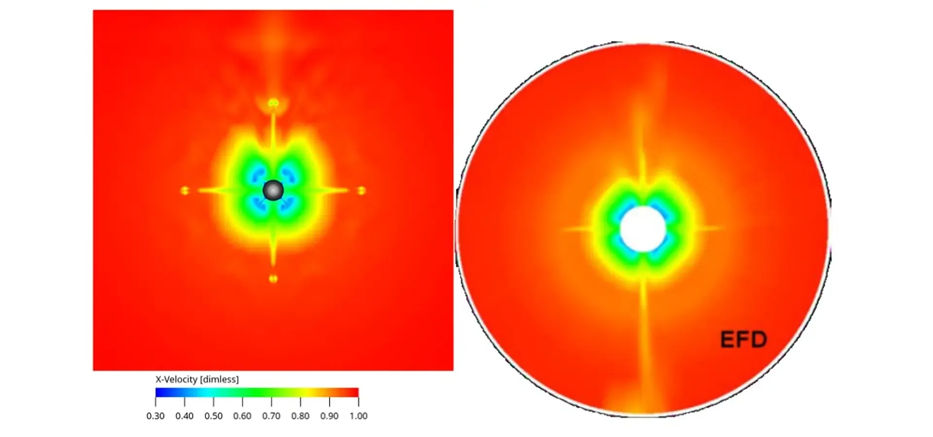
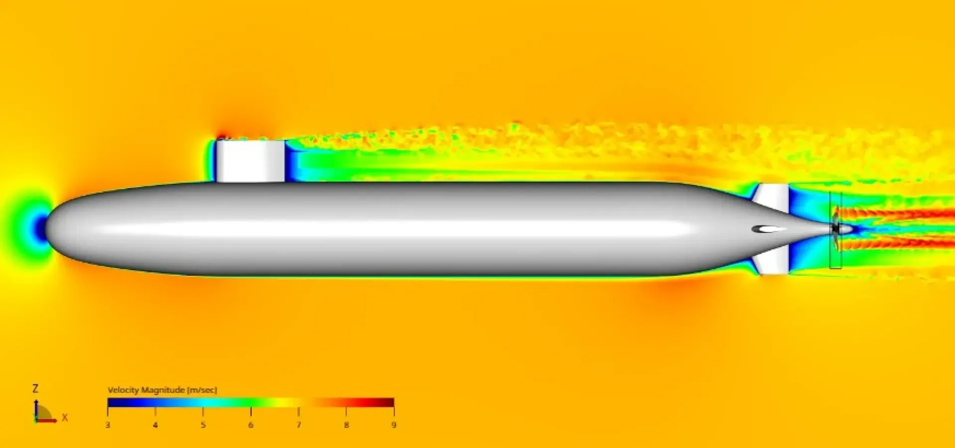
The simulation reveals several features of the submarine wake. First and most obviously, there is a very high wake velocity in the immediate vicinity of the propeller. Secondly, there are four clear projections in the wake caused by the four appendages at the tail. Third, there is a faint wake from the sail on top of the hull. Although minor, this can still interact with the propeller wake and cause instabilities. All of these are visible in both the simulation and the measurement. A fourth characteristic is visible in the simulation data – vortices from the tips of the appendages. These are not visible in the measurement data due to the limited resolution of the PIV. In this case, the simulation reveals behavior missed by the measurement.
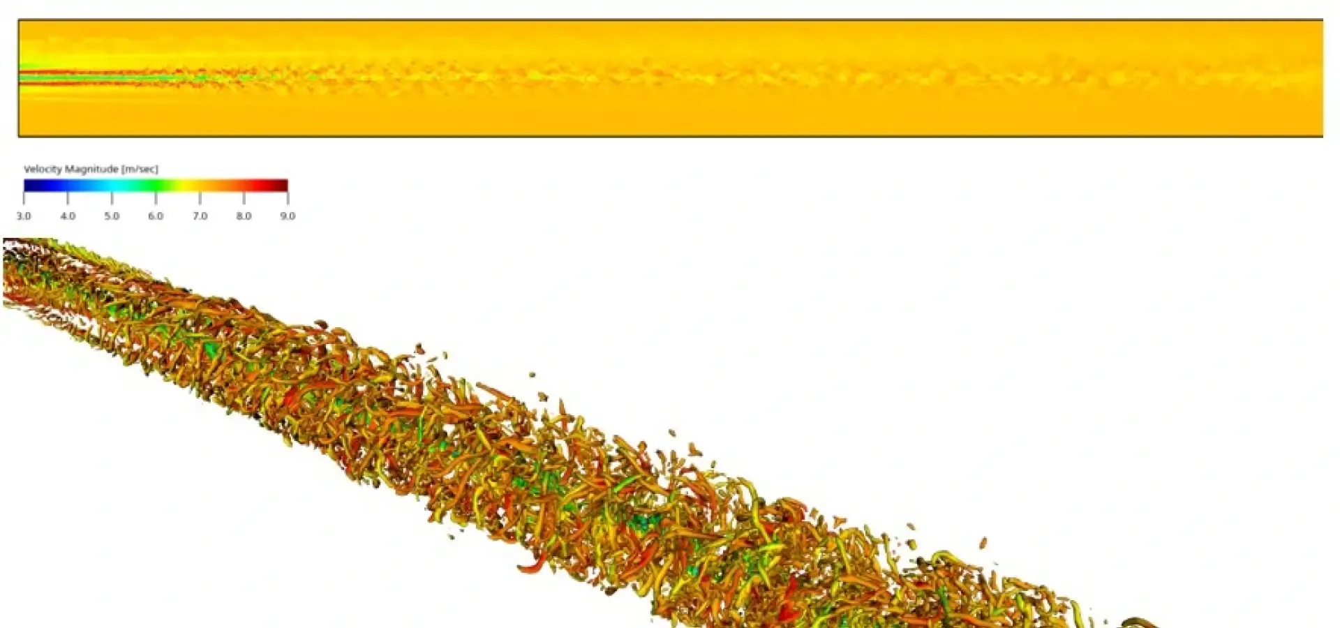
We can also analyze the far wake. The efficiency of PowerFLOW for turbulent flow allows us to simulate a length of 10 submarine lengths behind it. By understanding the far wake and its impact both on the hydrodynamics as well as acoustics, engineers can optimize designs to reduce the wake behind the submarine and improve its stealth characteristics.
Conclusion
Simulation enables marine engineers to design more efficient and stealthier submarines. SIMULIA PowerFLOW is well-suited to the challenges of submarine simulation, using the Lattice Boltzmann Simulation to model the flow of fluid around the hull, including all appendages, and the propeller. The accuracy of PowerFLOW has been verified against established benchmarks, showing close agreement with the measurements. Simulation can be implemented as part of the design workflow using a unified modeling and simulation (MODSIM) workflow. SIMULIA PowerFLOW integrates with design tools such as CATIA and other SIMULIA simulation tools on the 3DEXPERIENCE platform.
Discover More
Explore our Industry Solution Experiences
Source : “Summary of DARPA Suboff Experimental Program Data” (1998) by Liu and Huang.
Source : “Simulations of the DARPA Suboff submarine including self-propulsion with the E1619 propeller” (2012) by Chase.