Clemson University
Clemson University wanted to build a real-time test bench simulation laboratory so that students or other non-experts could study the behavior of huge wind turbines in a controlled and repeatable environment.
The single biggest challenge to studying system-level wind turbine behavior is the stochastic nature of its natural driving force - the wind. Wind profiles corresponding to many of the design load cases are generally rare events, and if you are lucky enough to experience one in the field with a prototype turbine, you’ll never see one just like it again.
In consequence, engineers build test benches to allow them to controllably and repeatedly apply full-scale loads to wind turbine components. Wind energy conversion systems have experienced a steady growth in size through their commercialization and use in utility scale power production. But as wind turbine size increases, so too must wind turbine test benches, which have become larger and more complex than ever before and are impressive dynamic systems in their own right.
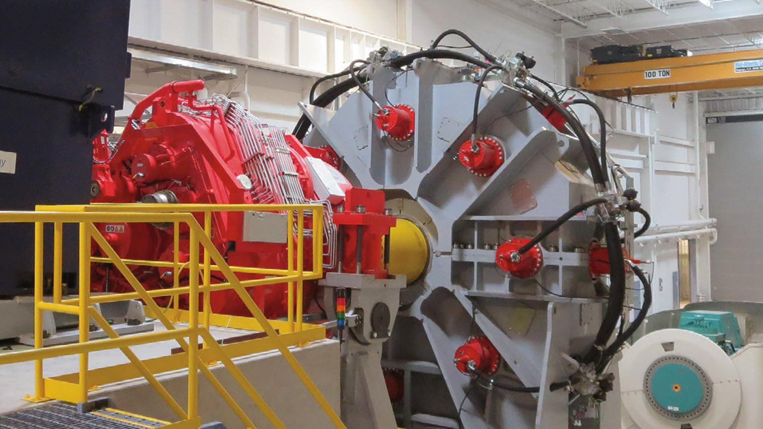
One such facility is Clemson University’s Wind Turbine Drivetrain Testing Facility (WTDTF) at the South Carolina Electric & Gas (SCE & G) Energy Innovation Center (EIC) in North Charleston. The WTDTF houses two wind turbine dynamometer test benches, one rated at 7.5 megawatts (MW) and the other rated at 15 MW. These test benches are designed to rotate fullscale nacelles while applying non-torque loads (thrust force, vertical force, shear force, pitch moment, and yaw moment). Additionally, the Duke Energy eGRID (electric Grid Research Innovation and Development) center, also located at the EIC, can load the nacelle electrically with an electric grid simulator.
The facilities at the EIC offer testing capabilities for the onshore and offshore wind industry as well as R&D opportunities for students and faculty at Clemson and partner universities. However, these systems are expensive to operate and require a high skill level for safe operation; it’s an environment not ideally suited to engineering students or other non-experts.
To help mitigate this situation, Clemson University is constructing a multi-body, real-time wind turbine test-bench simulation laboratory to serve as an intermediary between purely simulation-based analysis and physical testing. The lab consists of two primary pieces of equipment. The first is a duplicate test control computer from RENK Test Systems. The second is a real-time simulation computer from Concurrent Real-Time. This control computer is the human-machine interface to the test rig and is where the test engineer programs the test profile, executes the test, and monitors the behavior of the test bench.
The real-time simulation computer is for running dynamic models of the test benches, which interact with the duplicate test control computer in real-time. The actual simulations are managed by Concurrent’s SIMulation Workbench, a complete framework for developing and executing real-time HiL simulations. This tool allows for a SIMPACK multi-body simulation model to be relegated to specific CPU cores, isolating it from other models or processes and ensuring deterministic behavior.
The simulator accepts input signals from the test control computer, simulates the dynamic response of the test bench, and provides feedback to the test control computer. This is essentially a virtual test bench, which offers engineers the ability to evaluate proposed test profiles, troubleshoot unexpected behavior, and train personnel without ever having to use the physical test bench. Additionally, the lab will have controllers, I/O hardware, and data acquisition hardware so that engineers can replicate test-floor configurations in a laboratory setting.
The simulation lab makes the dynamics of the test benches accessible to students and faculty with zero risk compared to using the actual test bench. Practical applications of the simulation lab include test profile development, system troubleshooting, training, and pre-test communication validation.
The laboratory is designed specifically to replicate and study the dynamic behavior of the complete test bench, including both the device under test (DUT) and the test equipment (hardware and software). Many other researchers and manufacturers have studied the dynamic responses of wind turbines. The Clemson lab is focused on understanding the dynamic response of the complete test bench system, including the nacelle.
Multi-body modeling with Simpack
To better understand the dynamic response of the complete test bench, multi-body and dynamic models of the test benches have been created in Simpack and Simulink®. The complete test bench includes the DUT in addition to the test equipment.
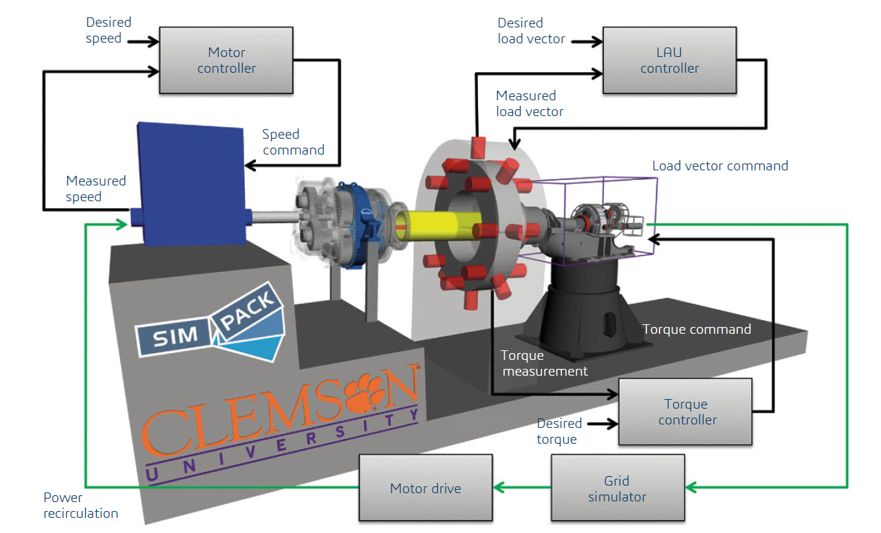
Components modeled in Simpack include the drive motor, high-speed couplings, 7.5 MW reduction gearbox, low speed shaft, load application unit disk, and nacelle, including main bearing, gearbox, and generator. The dynamic character of the DUT significantly influences the overall system response and therefore must be included in the modeling effort. Clemson University has been working with its first customer, General Electric, to develop representative dynamic models of GE’s wind turbine nacelle, also in Simpack.
Many of the component models have multiple versions with varying levels of fidelity, allowing the complexity of the overall model to be aligned with specific modeling goals. The system model is divided into naturally occurring subsystems in both Simpack and Simulink. Senders, Receivers, and Substructures are used heavily in Simpack, making the model easy to reconfigure and work on. Different gearbox model versions all have the same input, output, and support Markers making it easy to reconfigure the model for high and low fidelity simulations.
In addition to multi-body systems, the test benches include hydraulic, electric, and control system models all functioning simultaneously to produce an overall system response.
The governing equations for these various subsystems were developed analytically and coded in Simulink. These models interact with the Simpack model using Simpack’s co-simulation feature or the S-function model export feature. The complete model couples the behavior of the multi-body and non-multi-body systems.
Simulating a full-scale mechanical and electrical response
The ultimate goal is to replicate a nacelle’s response to full-scale mechanical and electrical loads in a controlled and repeatable environment. Replicating such a response requires two hardware-in-the-loop simulations operating simultaneously - one mechanical and one electrical. This is an advanced testing strategy and making it a reality is challenging.
Engineers at eGRID are currently developing dynamic models of the facility’s power systems and future goals include coupling the mechanical (WTDTF) and electrical (eGRID) models to form a single, facility-level, dynamic model. The availability of such a model will help to make this testing strategy a reality.