CATIA - ELECTRICAL SYSTEMS ENGINEERING
Adapt to change by innovating
with efficient collaboration

INTRODUCTION
Today Industry faces many challenges. The market is demanding smarter products and new innovative solutions. Products and services are getting connected, autonomous and more complex involving new requirements and stringent regulatory standards to keep up with new technologies. Production methods and techniques are also changing and the need for collaboration and innovation has skyrocketed.
A direct consequence is that more and more software, electronics and electrical engineering are involved in making the products. This brings additional challenges to the electrical engineering disciplines such as rising costs, additional quality issues and shortening time-to-market. In addition, this further adds to the complexity of integration with other engineering disciplines such as mechanical, fluidic and software.
This e-book will highlight the Dassault Systèmes solution and how to tackle an end to end electrical process and integrate it within a full development project.
CHALLENGES
- Many traditional engineering firms and departments use a wide assortment of specialized software applications to create and manage fluid and electrical systems.
- Each of them, with their own database schema or file-based information storage, results in inefficient manual exchange of data between essential process steps.
- There is not a strong enough link between: Schematics and 3D design and manufacturing,
- Electrical teams are critical departments that undergo engineering changes last.
To remedy these common challenges, the first step is to have a comprehensive and integrated design workflow that accesses a single source of truth for all stakeholders
VALUE PROPOSITION
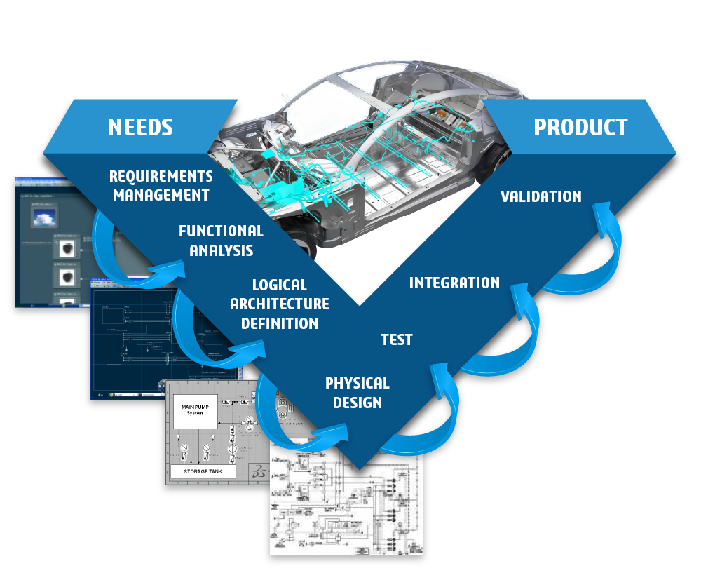
Process overview


System architecture and topology
CATIA IS EXTENDING THE ELECTRICAL HARNESSES DESIGN PROCESS TO MODEL BASED SYSTEMS ENGINEERING.
Very early in the design process, it is possible to review systems architectures, 3D architectures mock-up and equipment and net list.
This is done through the creation of a collaborative architecture mock-up in which we have systems zones or packaging, equipment and interface definition, signals information and engineering rules.
The aim is to offer a unified referential including all engineering disciplines, optimize the design during the preliminary phases, make trade off scenarios driven by KPI and requirements.
Schematic
CATIA ELECTRICAL SCHEMATICS 2D APPLICATION IS FULLY INTEGRATED INTO THE 3DEXPERIENCE PLATFORM.
It benefits from PLM and collaboration capabilities. It is also integrated within an end to end process including Model Based Systems Engineering and 3D design.
- The application allows you to create generic net and wiring diagrams. It also shares data with the system architecture and the collaborative architecture design.
- By knowing equipment and interface lists, signals and connections details, CATIA can automatically generate schematic diagrams.
- Automatic checks and KPIs guide you to provide consistent deliverables.
- The schematics specify the electrical Harness 3D-detailed design. This offers a full digital continuity and traceability.
Harness 3D-detailed design
CATIA’S POWERFUL WIZARD ALLOWS A GAP ANALYSIS BETWEEN 2D AND 3D LAYERS.
Electrical Harness 3D-detailed design has strong links with schematics.
Cross-highlight between the two definitions helps you make better decisions and update the 3D design accordingly. Equipment, connectors and wires are positioned automatically. The designer only has to focus on the detailed design, position supports, create branches, route wires, add protections and update the bundle geometry.
Engineering rules make it possible to perform a high-quality design. Finally, the Harness 3D-detailed design is a direct input to the manufacturing step and drawing generation.
Manufacturing
CATIA ELECTRICAL HARNESS DESIGN PROCESS INCLUDES HARNESS MANUFACTURING.
There is a full synchronization between the 3D design,flattening and drawing generations steps.
Each modification is taken into account through a dedicated assistant and allows you to update the flattening view as well as the drawings.
This ensures full continuity from the schematics and 3D detailed design without any export/import manipulations. The manufacturing application also offers great features to configure the automatic drawing generation to easily flatten the electrical harness and to analyze torsion in flattened branches.
Validation and governance
CATIA ALSO OFFERs A SET OF APPLICATIONs ALLOWING a LINK WITH REQUIREMENTS MANAGEMENT, EMBEDDED ELECTRONIC ARCHITECTURES AND BEHAVIOR SIMULATIONS.
This allows you to perform validation and verification using parameters, implementation links, drop voltage calculation and electrical and thermal simulations.
Being part of the 3DExperience platform, the electrical data managed by CATIA apps is accessible by others solutions like SIMULIA to perform EMC simulations
The 3DEXPERIENCE platform is a business platform, so every designed objects is part of a collaborative space has its own life cycle and modification process and is part of projects and shared in communities.
Conclusion
CATIA - Electrical Systems Engineering
CATIA - Electrical Systems Engineering is an End to End solution that covers the whole process from systems architecture to harness manufacturing using seamless and connected applications.
Many existing processes are implemented using different tools. These isolated processes result in heavy modifications costs and position the electrical design late in the process. By promoting collaboration with other disciplines like fluidic, HVAC, mechanical, engineers can better make decisions and create high quality products with a shorter time to market.
Learn more


