For the last several decades, bigger automotive engines were considered more reliable, powerful, and faster. However, today’s emission regulations are more stringent, and future regulations are pushing designers toward ever greater engine efficiency. In 2004, the European Union passed the EU5 standards, which went into effect in 2009 with the lowest CO2 limits yet (140g/km). Environmental regulations are now providing the impetus for moving toward smaller, more efficient engines—and designers and manufacturers alike are realizing that small can be beautiful.
Green Doesn’t Mean Losing Get-Up-and-Go
“Consumers want greener cars, but they want them to have the same performance as their older, larger models,” said Mark Stephenson, Chief Engineer of Predictive Analysis at MAHLE Powertrain (MPT), a leading international engine development partner and manufacturer in Northampton, U.K. In the quest for improved operating efficiencies, automotive engineers have tried direct injection, variable valve trains, controlled auto-ignition or homogeneous charge compression ignition, and engine downsizing.
In search of a green, gutsy engine, MPT chose the downsizing strategy and put the company’s 50-plus year legacy of engine acumen to work on designing a demonstration model that would decrease engine size by a whopping 50 percent and, as a result, cut fuel consumption by 30 percent—all the while delivering comparable performance.
“There has been a significant increase in the number of downsized engines on the market, with more to be introduced in the near future,” said Stephenson. Downsized engines currently available include the Audi 2.0 liter-TFSI, the BMW 3.01 liter Twin-Turbo, the Mazda 2.3 liter Turbo, and the VW 1.4 liter TSI, which are all 25 to 30 percent smaller than the NA (naturally aspirated) engines they replaced. But the MPT team wanted to go even smaller.
To meet the small-yet-powerful goal, the team first chose a 2.4 liter V6 PFI (port fuel-injected) engine as the size and performance standard—typical of a Class C or D European vehicle platform (circa 1600 kg). They then set their sights on replacing it with an aggressively downsized, state of- the-art, 1.2-liter, three-cylinder, inline engine—the I3. To be comparable with the 2.4 liter V6 configuration, the I3 engine needed to meet the performance targets for torque and power of that engine—286Nm torque at 2500 to 3000 rpm and 144kW maximum power at 6500 rpm.
To minimize size while maximizing performance (high specific power output), the design objectives included the use of a twin turbocharger system combined with state-of-the-art direct-injection technology and variable valve timing.
In addition, the MPT team made the decision to manufacture the engine entirely out of precision-cast aluminum, using MAHLE’s proprietary Coscast process, a solution that substantially cuts weight while providing superior performance.
Studies have shown that improvements in fuel economy are possible with increased levels of downsizing. “But as specific output increases, so do the technical challenges,” said Stephenson. Those challenges include: a robust combustion system that allows a high compression ratio to maintain partload efficiency; good low-speed torque and transient performance; real-world fuel consumption benefits through a reduction in full-load fuel enrichment; and engine robustness and durability. “With a long list of technical challenges,” said Stephenson, “we rely on finite element analysis to guide, validate, and optimize the design.”
Abaqus FEA Drives Successful Downsizing
For about a decade, MPT has been using Abaqus FEA as one of its primary analysis tools. “We originally chose Abaqus because we considered it the best tool for solving the day-to-day nonlinear problems we encounter, such as those involving plasticity and contact, as well as for its ability to perform thermal and NVH simulations” said Stephenson. The broad range of capabilities in Abaqus was also important, as designing an entire engine from the ground up involves many components, a host of separate simulations, and a variety of other specialized software tools (both in-house and commercial).
The big simulation picture for the I3 required the delivery of optimum levels of friction, weight, durability, and robustness to support future requirements as an R&D platform. In addition, the engine design was to be a “blank slate” approach that was not constrained by previous engine designs and manufacturing requirements. “The concept approach was based on the use of technology that would ultimately be available for mass production techniques,” Stephenson said.
With all of these factors in play—power output, gas exchange, combustion, friction, durability, manufacturability—the role of unified predictive finite element analysis was paramount. Stephenson’s team utilized Abaqus to perform studies of all the main engine components, including structural analysis of the crankshaft, thermomechanical analysis of the head and block assembly, and thermo-mechanical analysis of the exhaust manifold.
From Zero to Sixty in Three Simulations
The Crankshaft Analysis: At the heart of the engine is the cranktrain, and at the heart of the cranktrain are the crankshaft and connecting rod. In downsized engines—with very high specific output required and very high combustion pressures resulting—the importance of structural analyses of these two components is accentuated in order to achieve durability while keeping mass and friction to a minimum. Analysis of the connecting rod was relatively simple. But analysis of the crankshaft behavior was more complicated, as it included the dynamic loading of the connecting rods, pistons, pulleys, and the fly wheel, and also needed to account for torsional oscillations—all variables that Stephenson’s team were able to optimize by using a flexible multi-body model.
For this dynamic analysis, the team created a condensed substructure model of the crankshaft containing 340K elements, 435K nodes, and 1.66M degrees of freedom. They imported the model into AVL EXCITE (a straightforward process due to the partnership between SIMULIA and AVL), ran the dynamic simulation, and then used the deformation results at the retained degrees of freedom to drive the full Abaqus model in order to recover the stresses (Figure 1). With the stresses in hand, Stephenson’s group then ran a fatigue analysis for a full 720-degree cycle (two full rotations of the crankshaft), in the end determining the fatigue safety factors for the crankshaft. A submodel of the crankshaft journal fillets was subjected to an additional fatigue analysis to ensure that this critical region met durability requirements. Runtime for this analysis was 24 hours, utilizing a hardware set-up that was used for all analyses: 2 off 4x Dual Core Opteron 8222 3.0GHz Dell Blades, each with 32 GB RAM, running SUSE Linux.
The Head and Block Assembly Analysis: The head and block assembly is comprised of many components, including the latest direct injection technology with both injector and spark plug in the center of the combustion chamber—an arrangement that requires a more complex cooling jacket design. This required both a thermal analysis of the head and block assembly to ensure adequate cooling and a structural analysis to verify durability and head gasket sealing performance. The assembly—including block, bed-plate, nut plate, head bolts, cylinder head, head gasket, valve guides, valve seats, and valves—was extremely large, using 1.01M elements, 1.72M nodes, and 8.8M degrees of freedom (Figure 2).
For the thermal portion of the study, the team mapped htcs (heat transfer coefficients) for the cooling jacket onto the FE model from a CFD analysis. The results were used to assess the cooling around the injector and the effectiveness of the crossflow cooling configuration (Figure 3).
For the complex structural analysis, the team included: a full nonlinear definition of the cylinder head gasket (modeled using gasket elements and separate gasket properties for each region of the gasket); plasticity for the aluminum head and block; small sliding contact (with friction) between all mating components; interference fits between valve guides, seats, and the head; and head bolt loads applied using pretension sections.
The total structural analysis required 10 separate steps (pre-assembly, cold assembly, and hot assembly and firing of each cylinder at hot assembly and cool down). In addition, the team evaluated the pressure of the gasket beads for all firing cases, as well as the durability of the entire assembly, once again performing a fatigue analysis—for high cycle fatigue (hot firing) and for low cycle fatigue (hot assembly to cool down). Runtime for this extremely complex structural analysis was more than 12 days (290 hours) and served to validate the MPT team’s downsized engine design decisions. With some small changes to the head design, MPT was able to ensure that temperatures remained within limits and that gasket sealing was good.
The Exhaust Manifold Analysis: With a high-pressure turbo housing integrated into the exhaust manifold, Stephenson’steam determined it necessary to conduct a transient thermo-mechanical analysis of the manifold to test the durability of the system. The team used this simulation to mimic an exhaust manifold crack test and structured the heat-up and cool-down test in three steps—seven and a half minutes at maximum power, followed by two and a half minutes at 3000 rpm, followed by a repeat of the first step.
The exhaust model was constructed with 147K elements, 410K nodes, and 1.21M degrees of freedom. From this simulation, the MPT team determined that the maximum stresses to the manifold occurred approximately 30 seconds into the heat-up or cool-down cycles (see Figure 4). They also evaluated manifold durability by comparing the plastic strain amplitude over one cycle to the strain life data for the manifold material. “In the end, our designs were once again validated,” Stephenson said, “and only small changes were required in order to improve durability.”
From Test to Track to Thruway
“At MPT we do everything from design concept to manufacture,” said Stephenson. “The designers give us their first cut and we analyze it and do two or three design iterations.” In this case, analysis ensured that performance targets were met, the engine was durable, and the mass of all
components was achieved.
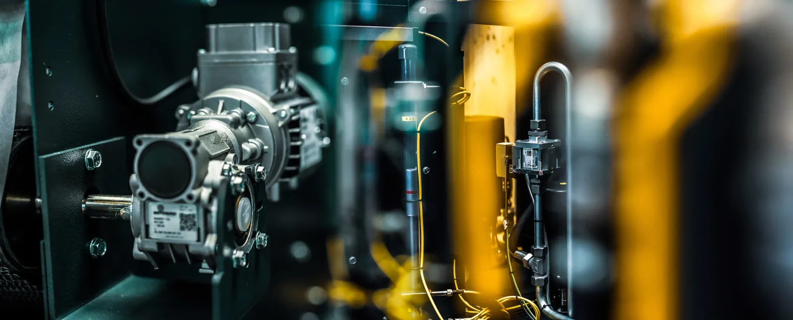
At this stage, the I3 engines are concept level, not final designs. But as demonstration engines, their role is quite important, because they are used to test systems, new component designs, and even new fuels and oils that are in development. What’s more, the I3 holds even more promise for MAHLE according to Stephenson. “We sourced as many of the components as possible from the MAHLE Group,” he said. “So in the end, this engine is really the showcase of MAHLE’s—as well as our R&D group’s—capabilities and technologies.” (Figure 5)
For now, MPT has built several demonstration I3 engines that are currently racking up hours on indoor test beds at the company’s Northampton facility. In the first half of 2010, though, they will find themselves under the hood of a car and accumulating miles on the roads of Northamptonshire. Beyond that, MPT’s goals for the new small but lively I3 almost certainly include a public introduction on local thruways—as part of the next generation of environmentally-friendly vehicles—thanks to engineering innovation and realistic simulation.